This thread has been locked.

If you have a related question, please click the "Ask a related question" button in the top right corner. The newly created question will be automatically linked to this question.

TDA4VM: OpenVX Viss kernel support

Part Number: TDA4VM


Dear Team,

Please kindly support my customer CNH Industrial with their TDA4VM implementation. Details below:

I would like to ask for some support concerning the TDA4VM platform, more specifically on the OpenVX Viss kernel. I am currently inputting a raw GB-bayer format image, and I would like to retrieve the R, G, and B channels. I saw this was possible from the documentation online if I set the fcp mux correctly. Now, I am getting three planes back and I write them to disk (in subsequent nodes), but, the output does not form a correct RGB image.


Parameters and code

I extract all three channels in three separate VX_DF_IMAGE_U8 as referenced by the documentation.

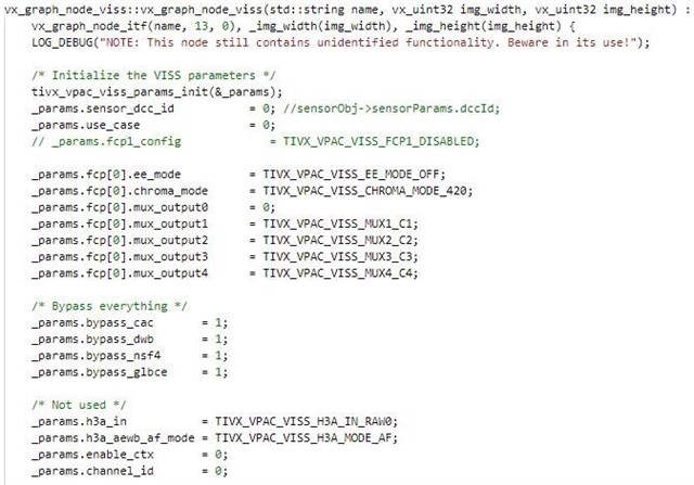
The configuration is set as follows (every subsystem is bypassed as I’m currently only interested in the debayering functionality)

The target is set to

TIVX_TARGET_VPAC_VISS1

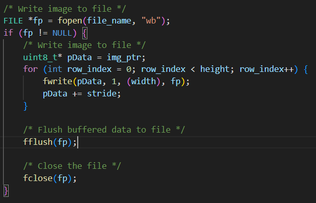
And I write the image as follows in a custom CPU targeted node

Outputs

I currently receive an output where the red channel seems to be fine, but both the green and blue channel have weird things happening. I think the green channel shows only the bottom, the blue only the top. And also, every second on every row apart from the first is set to zero. This makes that the image simply does not make sense.


Could you help me with this issue or forward me to the correct support?

Do you also have some additional documentation on the exact algorithms that are implemented in the VISS node for reproducability?

  • As an update,

    The customer managed to instead of capturing the R, G, and B outputs, capture the C1-C4 outputs which supposedly gives me the direct outputs of the CFA. They have managed to recreate an RGB images from this, but the contrast is not acceptable. They cannot use these images for any detections and a simple bilinear interpolation works much better. Is there any way to improve this VISS node output? They have tried playing with the other parameters of the VISS node, but without luck.

    (As reference for reproducibility, they used the parameters indicated in the code above, but simply captured the C1-C4 outputs instead of the RGB outputs)

    Thanks,

    Daniel

  • Hello Daniel,

    The thread has been assigned to OpenVX/VISS experts based in India. Since today is a regional holiday in India, please expect a 1-2 day delay in response.

    Thanks.

  • Hi,

    If you are getting RED color output, then it should also work for other two color outputs. no reason for it not work as long as the correct image file is provided. Looking at the code above, VISS parameters seem correct, can you also share VISS create node code?

    Regards,

    Brijesh

  • Hi Brijesh,

    Configuration based on C1-C4.

    Creation of the inputs and outputs (C1-C3, I ignore C4). When capturing the RGB output, I would change the image type from VX_DF_IMAGE_U16 to VX_DF_IMAGE_U8 for all three images.

    Finally, when I captured the C1-C3 output, I got the following images.

    (raw output)

    (after white balance, based on a known color strip)

    As you can see, the problem here is that the color contrast is not correct. A correct image looks like this:

    (before whitebalance)

    (after whitebalance)

    We can get a correct image from using the OpenCV debayering process (GR bayer format) in Python, but not with the VISS node. I have attached a raw image here for you to try on.

    This is a binary U16 format in bayer GR (following OpenCV standard), we sometimes use GB format since this only switches the red and clue channel. Using GR will generate a blue-ish image, using GB will generate a green-ish image like above.


    The following Python code can read the image, reshape is correctly, and the converts from bayer to RGB format.

  • Hi Daniel,

    As per below table, as given in TIOVX node's documentation, the max value of C1 to C4 does not output RGB data, instead it is used to output CFA output. Can you please chanage the value of these muxes, espectially mux2 to mux4 to value 1 to get the RGB data output? 

    Regards,

    Brijesh

  • Hi Brijesh,

    As per the first post, they already tried the RGB output and nothing comes out of it. Changing this makes it even worse.

    As for the CFA, I assumed it was the debayering process and since our raw images are inputted as an RGB bayer format, I could extract them like this.

    Thanks,

    Daniel

  • Hi Daniel,

    I checked regarding this internally and currently only YUV422 and YUV420 outputs from VISS is tested. RGB and CFA are not tested.

    May I know if they could use YUV422 as output for their usecase?

    Regards,

    Nikhil

  • Hi Nikhil,

    The customer also tried YUV in the past, but after conversion of the YUV to RGB, they got similar issues with the contrast.

    Best regards,

    Daniel

  • Hi Daniel,

    Are the YUV422 output correct? Could you please confirm this?

    Regards,

    Nikhil

  • Hi Nikhil,

    Based on what they communicated, yes.

  • Hi,

    In that case, if the YUV422 output is correct, then there is no issue with the VISS output. Now we would have to focus on the way of converting YUV422 to RGB. Could you let me know how they did this?

    Regards,

    Nikhil