This thread has been locked.

If you have a related question, please click the "Ask a related question" button in the top right corner. The newly created question will be automatically linked to this question.

AM5708: Automotive Production Boot Mode From SD Card: Is there an I/O pin indicating Global Warm Reset

Part Number: AM5708

Hello,

I have an AM5708  Silicon version 2.1 System that boots from an SD card, and has a boot vector SYSBOOT(15:0) = 0xA330. This corresponds to Automotive boot mode from SD Card.

I didn't design this system, and it has yield issues. About half the time the CPU will not have any console output. 

The SD Card is attached to MMC1 port.. The console is attached to UART1. 

1) Is SYSBOOT15 being tied to a one a problem? Is it only a problem if MMC2 is used to Boot? 

2) I was reading in the SPRUI30G chapter 32.2.4 SYSBOOT Configuration, which seems to indicate that if the boot fails the chip will perform a "Global Warm Reset." 

Is there and IO pin that indicates this the chip is performing a "Global Warm Reset?"

Jeff Cohen Hubbell Power Systems, Boonton, New Jersey.  

  • Hi Jeff,

    This thread has been assigned. Please expect a delay in response as the assigned engineer is out of office till Apr-11.

    Regards,

    Takuma

  • Hello 

    For Q2, please see the rstout pin on the Datasheet.

    Will reassign to our board engineer for your initial query.

    -Josue

  • Hello Josue,

    I see that RSTOUNTn (Ball E20) goes low for 250US every 53ms. I have a 100K pulldown and it goes GPIO_1 pin 13 of the TPS659163 PMIC.

    Doe this indicate that there was an error in reading the SD Card? The SD card  is good because will boot in another circuit board.. 

    Is the value of the SYSBOOT (15:0) = 0XA330 correct? 

    Thanks,

    Jeff

  • RSTOUTn is a good indicator for processors internal reset status:

    I don't see any errors with SYSBOOT.

    [5:0] 0b11 0000: Production boot for SD (after 10 failed loops ROM will initiate a reset)

    [7:6] 0b00: 00 (QSPI specific)

    [9:8] 0b11: 19.2MHz SYS_CLK1 (assume this is correct0

    [13:10]: 0b1000 (GPMC specific)

    [14]: 0b0 (Fixed to 0)

    [15] 0b1 (Impact is for MMC2), assuming you have on-board pull-ups for MMC1

    Be aware of the note for table 4-20 eMMC/SD/SDIO Signal Descriptions in the data manual:

  • I can see that the SD clock on a board that boots is 400KHz. On the boards that do not boot the SD Clock is trying to go high, but it does not go above a half Volt. There is a 33.2OHM 0402 1/16W series resistor that was placed in the middle of the trace, and there is a Not-Populated 10KOHM pullup.  I see that the recommendation in the schematic checklist SPRACK7B is 22OHMs. The clock trace is not impedance controlled. 

    Is the difference in the series resistor value significant? What is the drive strength of the SD Clock?

    The clock trace length total is about half an inch longer than the data and Command lines. Is there a recommendation for SD lines for impedance and length matching?

    Jeff

  • Series resistor should NOT be place in middle of trace, but close to source (processor).  Value should be 22-ohms, not 220-ohms.  Traces should be 50-ohms and all signals should be length matched (0.5" skew is likely OK). 

    The clock reaching only 0.5V IO is a problem.  Have you checked all power rails?  The IO rail for MMC1 is VDDSHV8 - can you confirm its 3.3V (or 1.8V) is has correct power-up timing (from data manual)? 

    0.5V IO could also be from contention - can you check to make sure nothing is shorted on the board (ESD diode, etc)?

  • The series resistor is 33 point 2 Ohms. I change this to 22OMs and I will move it in the next spin of the board,. I will also fix the trace widths for 5o OHM impedance. All of the traces are within the 0.5".  I will change the resistor to 0603. I think that the factory cannot reliably mount the 0402 parts. 

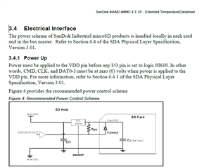
    Also: While I have your attention: MMC1 controller VDDSHV8, and the SD card is pulled up to LDO1 (3.3V). The SD card power is enabled by REGEN1. There are 2.5ms between REGEN1 and LDO1 coming up. I observe that LDO1 is coming up about 7ms before the SD card is powered up. This violates the SD card spec. The SD Card should be powered up before the SD Card IO pins have Voltage, but it seems to work. As far as I know I am not using UHS mode. Is it safe to power the SD card from LDO1?

  • I don't have the SD card spec available to verify.  LDO1 possibly used to power both VDDSHV8 and VDD of SD card if it has the current capacity (not use SD card power requirements) and if supply is fixed 3.3v (not using UHS-I modes that switch to 1..8V) 

  • I don't have the SD Spec either. I found the information in SanDisk industrial SD Card Datasheet.  Using LDO1 is risky. LDO1 can output 300mA max The SD Card is 150mA or 200mA for 50MHz. I have no idea what the SW is doing.  How much current dies the MMC1 controller draw?

  • The MMC1 controller is not powered by VDDSHV8, only the IO cells.  

  • I should have enough current capacity. 

    Thank you very much for all of your help.