This thread has been locked.

If you have a related question, please click the "Ask a related question" button in the top right corner. The newly created question will be automatically linked to this question.

TDA4AL-Q1: Is there any method to adjust the eMMC data delay to make the timing meeting the spec for HS200?

Part Number: TDA4AL-Q1


Hi expert,

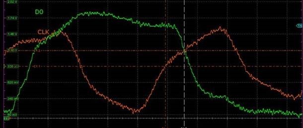
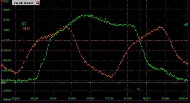
In the spec of eMMC, it is required that the minimum data hold time should be 0.8ns. But in the actual measurement, customer find the hold time of the most data lines cannot meet this requirement. So customers would like to know if we can adjust some parameters/registers to make the timing in the spec? Thanks  

DAT[0]0.5963ns

DAT[1]0.6972ns

DAT[2]0.6039ns

DAT[3]: 0.519ns

DAT[4]: 0.85ns

DAT[5]: 0.8448ns

DAT[6]: 0.627ns

DAT[7]: 0.752ns

Best Regards,

Xingyu Zhu

  • Hi Xingyu,

    Thanks for providing some examples of the input timings you have captured. It does seem like the measurements vary quite a bit since the lowest one was 0.519ns and the highest was 0.85ns.

    First I'd like to ask how is this being measured and standardized? It also seems like the waveforms aren't super well defined and have a bit of static. I would recommend using tip and barrel measurement for the most clear waveform. Another thing to look at is to make sure the trace length follows the spec for our board which could help with a clearer waveform as well.

    Best Regards,

    Matt

  • Hi Matt,

    Thanks for your reply. Customer has provided the clear waveform as attached. They measure the signal close to the pin and follow the eMMC spec to capture the measure point.

    emmc timing waveform.rar

  • Hi Xingyu,

    Could you provide a screenshot of the timing waveform like previously? Thank you. 

    Best Regards,

    Matt

  • Hi Matt,

    Please check below screenshot.

  • Hi Matt,

    May I know if there is any further findings? Thanks

  • Hi Xingyu,

    Thanks for your patience. After discussing the waveforms with my team, we found that the clock STARTING to transition and the data STARTING to transition is 1.2ns - 1.5ns in your screenshots. Therefore, the small hold time you are measuring is due to the non-ideal slope/shape of the measured waveform transitions.

    Some of the non-ideal transitions can probably be attributed to measurement artifacts (probe point location, probe ground location). You could run an IBIS simulation on the system using ideal probe points (directly on the eMMC pins) to compare against their measurements.

    The rest of the non-ideal transitions may be attributed to the board/PCB. We can also help review this if you can provide the following:

    • Schematics of the full eMMC traces
    • PCB propagation delays of all traces

    Best Regards,

    Matt