This thread has been locked.

If you have a related question, please click the "Ask a related question" button in the top right corner. The newly created question will be automatically linked to this question.

AM6442: Using UDMA for continuous slave McSPI transfer

Part Number: AM6442
Other Parts Discussed in Thread: SYSCONFIG

Hello,

We have the following system architecture:

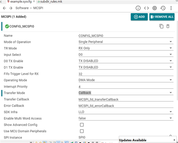
We are using the ADC as an SPI master and we would like to use McSPI1 and McSPI3 as slave controllers, that in an R5F0 application. The idea is to configure the UDMA in a way, that we basically implement endless circular reading, i.e.

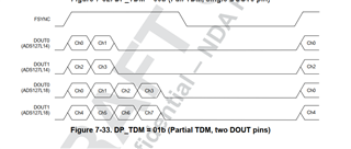
- The ADC is configured for delivering 32-bit data frame, using 2 DPORTS (Ch0-3 on D0, CH4-7 on D1). The sample rate is configured to 128 KSPS, which results in 32,7 MHz data clock

- The DMA is provided with a buffer in MSRAM, which is 16KB (for example)

- The DMA is configured in a way, that it delivers an interrupt for each 32 packets read (32xFSYNC), altogether 512 bytes (4ch x 4 bytes x 32 frames)

- After delivering the interrupt, the DMA continues with the next 32 packets and the target offset in the memory is incremented with 512 bytes

- The process continues, until the buffer end is reached, then the DMA should start from the initial buffer offset

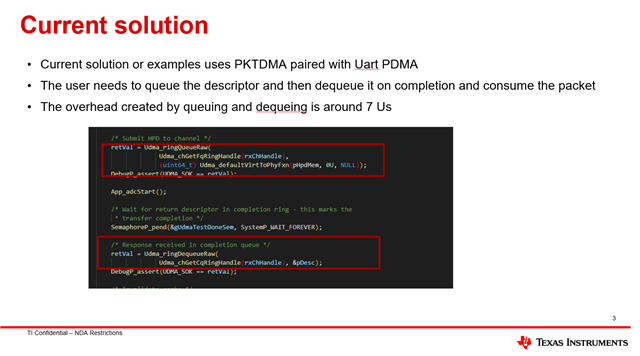
This was trivially achievable with other controllers (ST), using either DMA in circular mode and 1/4 Full, 1/2 Full and Full interrupts, or Double-buffering. With other SoCs (Xilinx) that was achievable trough programming the scatter-gather DMA structures and descriptors.

The problem we see with Ti, is that there is no practical guide how to use the UDMA, or at least we were not able to find one. The examples that could eventually help and that are provided with the MCU+ SDK, are using BCDMA, which I am not sure if it works in our case.

Any advice will be highly appreciated.

Thanks!

  • Hello Angel Gavrailov,

    I am looking at your queries, and you may expect delayed replies as I am in training entire next week.

    Regards,

    Anil.

  • Probably in the mean time, you could engage someone else too? 


    Thanks!

  • Hello Angel Gavrailov,

    Sorry for the inconvenience. All our team members are going to the same training .

    I will try to provide some suggestions on how to achieve the above use cases and try them at your side.

    I will try to share them by EOD.

    Regards,

    Anil.

  • Hello Angel Gavrailov,

    Sorry for the delayed reply.

    In TI we don't use slave and master words .So,  we use Slave mode as  Peripheral Mode and Master mode as Controller .

    So, for your use case we need two MCSPI's.

    One for reading 4 channels and the second one for reading another 4 channels.

    So, configure the DMA interrupt for 512 byes. So, for every 512 bytes you will get an DMA interrupt and in that interrupt you do process with the received buffer.

    I really don't understand what your expectation is to trigger DMA interrupt for 1/2 Buffer or 1/4 buffer filling or etc  rather than 512 bytes.

    Can you please elaborate on this case to better assist you?

    Actually, what is the use of FSYNC connected to SOC ?

    In the current MCU+SDK there are no examples of MCSPI in Peripheral mode with DMA.

    But, we support MCSPI+ Controller  Mode. So, with the existing example, we can achieve your requirement.

    You can take the example below and load it from CCS.

    C:\ti\mcu_plus_sdk_am64x_09_02_00_50\examples\drivers\mcspi\mcspi_loopback_dma_lld\am64x-evm

    You need to set the parameters below for Peripheral mode . The same example can be used for your requirement .

    Just you need to update the DMA length and one more thing I have noticed that in Peripheral mode DMA call back is not registering .

    So, we need to register DMA callback as well. Can you please use the above attached  example  and will  try to fix other issues while you are working on your example  ?

    Regards,

    Anil.

  • Hi Swargam,

    I already tried that mode (Peripheral+DMA). There were two problems:

    1. The code always got stuck in the DMA interrupt routine in MCSPI_udmaIsrTx in mcspi_dma_udma.c here:

    The reason is, that peerData  was always exactly 304 bytes bigger than effByteCnt, the expected byte count. The data reception was initiated with 

        auto status = MCSPI_lld_readDma(mIfDescriptor.spiHandle,
                                        storage->data(), storage->size(),
                                         1000,
                                         &extendedParams);

    2. The DMA interrupt performs a Tear Down of the DMA channel, when the transfer is ready and this channel needs to be reloaded then again with the above call. According to TI's own papers, it takes at least 7us to do that. We don't have that time, as we get samples each 8us, so from the end of a DMA transfer until the begin of the next one we only have maximum 8us in theory, in reality about 4us.

    Actually, what is the use of FSYNC connected to SOC ?

    FSYNC is our CS signal for the McSPI in peripheral mode.

    According this post: https://e2e.ti.com/support/microcontrollers/arm-based-microcontrollers-group/arm-based-microcontrollers/f/arm-based-microcontrollers-forum/1215616/questions-about-dmss-bcdma-pktdma-and-pdma/4597533?tisearch=e2e-sitesearch&keymatch=uart_rx_dma%2525252520bcdma%2525252520example#4597533  and your colleague Anshu Choudhary, the required behavior is only achievable trough BCDMA, since PKDMA does not support auto-reload.

    A similar example as the above post for McSPI would be very helpful.

    Thanks and regards,

    Angel

  • Any news there? I tried to port this example by changing the peer to MCSPI1_CH0_RX and configuring the rest accordingly, unfortunately I have no idea how to debug the application - DMSS and BCDMA is a very complex topic and will take a lot of time for us do make a deep dive. I would strongly prefer an experienced person's know-how here.

    Thanks!

  • Hello Angel,

    Sorry for delayed replies.

    I was on leave yesterday and was on training last week.

    We can continuously discuss this topic.

    So, my first question is that 

    May I know why you enabled TX as well ? Do you need to transfer data to ADC from SOC ?

    If this is the case, then what is your Tx and RX pins? How did you configure them in the system config?

    My suggestion is that we can try to stick with the MCSPI+PKTDMA and don't go with BCDMA since, as you mentioned, UDMA chapter is difficult and will take more time to solve the issues if we get during implementation and don't have  an examples .

    I understand your concern, so if you look at the driver dma_write/dma_read api, it's typically a combination of channel initiizations and then start DMA for each channel. After completion of DMA channels we are closing the channels.Again, when you need to start DMA again we, are initilizting the channels and starting the DMA. Here, you can notice every time why we need to initialize the channels in your case. 

    So, we can skip the teardown and initializations of channels in the driver for every each DMA start and completion respectively . And, for DMA, start and completion are typically done with the udma_queraw and udma_dequeraw functions, which are typically controlling DMA registers and do not take that much time. 

    Conclusion  , we will use the udma_queraw and udma_dequeraw functions for every DMA start and completion and will initialize the DMA channels for only one time.

    Please share the answers for above queries .Based on this, I can share the suggestions for  the driver updates.

    According to TI's own papers, it takes at least 7us to do that.

    Can you please point out the documentation for above one  ?

    Regards,

    Anil.

  • Hi Swargam, 

    May I know why you enabled TX as well ? Do you need to transfer data to ADC from SOC ?

    If this is the case, then what is your Tx and RX pins? How did you configure them in the system config?

    TX is not enabled on the RX Pin, in this case D0. We configure the ADC trough soft-spi (bit-bang) with the help of four additional GPIOs in order to avoid spending another SPI interface, as we already need 4 of them (2 for ADC, 2 for other high-speed peripherals).

    First of all, I don't find those functions that you mentioned. I only found Udma_ringQueueRaw and Udma_ringDequeueRaw.  However, rhe latter is commented with:

     *  Caution: Dequeuing from a ring (free queue) to which the UDMA reads
     *  should be performed only when the channel is disabled and using
     *  #Udma_ringFlushRaw API.

    That could be a problem or not, I don't know at the moment.

    Frankly speaking I really have a bad feeling for the solution you propose, since it involves interrupt handling and as I mentioned, we have only 2-3 us to react, meaning: DMA generates the completion interrupt request, the interrupt getting propagated to the core, the interrupt routine being executed and the dma descriptor enqueued. Normally, 3 us is a lot of time @ 800Mhz, unfortunately we are running a lot of other tasks in on this CPU and I cannot guarantee, that the dma interrupt will never be blocked either from another high-prio interrupt or from the FreeRTOS. Moreover, we have 2 SPI interfaces, meaning 2 interrupts to be handled.

    What I could imagine, is queuing more than one descriptor and get an interrupt on each descriptor's completion. This way the interrupt reaction time is not critical, as the DMA continues with the next descriptor. Unfortunately, from what I read, I don't see a possibility for PKTDMA to generate events on a descriptor's completion, but only on the complete queue. I hope I understood it wrong, but that could be done only trough BCDMA.

    Anyway, we can try to solve the problem the way you suggested, but I would be needing a guide how to exactly do that, as an example code, in the best case. 

    Can you please point out the documentation for above one  ?

    Sorry for the screenshot, apparently I cannot attach the complete file. That is from the above post (Link), there is a ZIP attachment and in the ZIP there is a PPT, please check page 3.

    Thanks and regards!

  • Frankly speaking I really have a bad feeling for the solution you propose, since it involves interrupt handling and as I mentioned, we have only 2-3 us to react, meaning: DMA generates the completion interrupt request, the interrupt getting propagated to the core, the interrupt routine being executed and the dma descriptor enqueued. Normally, 3 us is a lot of time @ 800Mhz, unfortunately we are running a lot of other tasks in on this CPU and I cannot guarantee, that the dma interrupt will never be blocked either from another high-prio interrupt or from the FreeRTOS. Moreover, we have 2 SPI interfaces, meaning 2 interrupts to be handled.

    Hello Angel,

    Yes, I agree with your point. The problem with PKTDMA is not reloading possible. So, every time we need to start the DMA for every transaction.

    I am trying to stick with MCU+SDK examples with some modifications in the driver. If we go for MCSPI+BCDMA then any issues comes it will take more time to fix these issues.

    What I could imagine, is queuing more than one descriptor and get an interrupt on each descriptor's completion. This way the interrupt reaction time is not critical, as the DMA continues with the next descriptor. Unfortunately, from what I read, I don't see a possibility for PKTDMA to generate events on a descriptor's completion, but only on the complete queue. I hope I understood it wrong, but that could be done only trough BCDMA.

    I assume that packet descriptor linking is possible. But here we may skip the queraw and dequeraw functionality for every packet descriptor, but we need to do queuing and dequeuing for every 2 second packet.

    I can check with other team members if there is any possibility to reload the packet infinite times in PKTDMA . So, that no need to start DMA for every each transaction.

    Anyway, we can try to solve the problem the way you suggested, but I would be needing a guide how to exactly do that, as an example code, in the best case.

    As of now, I have just split two functionalities, one for Channel initializations and another for DMA start.

    And after completion of DMA, I have not teardown the channels since we skipped channel initializations every time.

    I agree with your point querraw and dequearaw functions consume more time.

    I can internally check with the team if anyone implemented MCSPI with BCDMA. If any examples were there I can get back to you.

    Please look at the below example .

    mcspi_loopback_dma_lld_am64x-evm_r5fss0-0_freertos_ti-arm-clang.zip

    Regards,

    Anil.

  • Hello Angel,

    The above code given in controller mode and not in Peripheral mode.

    We configure the ADC trough soft-spi (bit-bang) with the help of four additional GPIOs in order to avoid spending another SPI interface, as we already need 4 of them (2 for ADC, 2 for other high-speed peripherals).

    My suggestion is that first we can complete the SPI, and later we can go with GPIO.

    With GPIO, it is possible, auto triggers DMA. If ADC gives the ready signal, then this signal will be input to the DMA.

    for e.g. 16 pins should be configured to Bank 0 .

    We need the one DMA channel per DRDY status pins to trigger the DMA .

    The source address would be GPIO DATA Register for DMA channel.

    Now, when the status pin change from either high to low or low to high, Hw can trigger the DMA automatically .

    So, for every change of GPIO Pin data is moved to destination buffer from GPIO DAT Register and this operation we need to do it continuously till x samples and after reaching the x samples, we can trigger the completion DMA event.

    Please refer below screenshot.

    Regards,

    Anil.

  • Hi Anil,

    Thanks for the detailed explanation above, but I am not really sure how to interpret it. I think you are reading the wrong ADC's datasheet. We use this one:

    https://www.ti.com/product/de-de/ADS127L18

    In this case there is no DRDY, and the ADC plays the SPI master (or Controller), by setting the FSYNC (CS) and clocking the data out trough D0 and D1    

    Can you confirm?

    Thanks!

  • Hello Angel,

    You are correct . Your ADC does not have a DRDY signal.

    Recently, some other users using different ADCs with the DRDY signal. So, I suggest the same method with the DRDY signal.

    Please don't consider above point if your ADC does not have the DRDY signal.

    Regards,

    Anil.

  • Hi Anil,

    the ADC we use is exactly that, what I mentioned in the link above. The only way to use it (as far as I know) is to let it be the master (peripheral) and clock the data in in the MCU. There is no workaround to use the MCU as master (controller).

    Regards!

  • Hello Angel,

    I am looking at your datasheet and by eod , I can confirm whether we can go SOC in Peripheral or Controller mode.

    This ADC driver has many features and needs to go through the datasheet .

    Regards,

    Anil.

  • Hi Anil,

    The problem is not the ADC, but the DMA.

    Regards!

  • So, In the mean time, I have found the solution (almost). Unfortunately, it requires a bit of hacking inside the drivers.

    Stage one:

    * Problem 1: the McSPI driver creates only one descriptor, when using the MCSPI_lld_readDma function. Means: when you want a slave transfer and call this functions, it ultimately populates only one HPD (Host Packet Descriptor) with the entire quantity of data to be read and pushes it to the PKDMA Free Queue. Thus, when the DMA finishes with this descriptor, it has noting more to do. The ISR handler is being called relatively soon (I didn't have the chance to measure the latency here), but until the next possible time, when a transfer is being able to be started again, more than 10us are gone. This is definitely too slow. 

    * Solution: Make it possible to chain more than one HPD, each with a different target buffer. Thus, when the PKDMA gets done with one, it still generates an event, and still the ISR is being called, but the PKDMA continues with the next HPD from the Free Queue. In practice: the quick and dirty solution was to duplicate the MCSPI_lld_readDma functionality, but wrapped in an own C++ class, containing the target buffers. Thus, the new function generates a separate HPD for each target buffer, with the required size. The core function to be modified is MCSPI_udmaConfigPdmaRx:

    Instead of:

        /* Update host packet descriptor, length should be always in terms of total number of bytes */
        udmaHpdInit((uint8_t *) dmaChConfig->rxHpdMem, rxBufPtr, (numWords << chObj->bufWidthShift));
    
        /* Submit HPD to channel */
        retVal = Udma_ringQueueRaw(
        Udma_chGetFqRingHandle(rxChHandle),
                              (uint64_t) Udma_defaultVirtToPhyFxn(dmaChConfig->rxHpdMem, 0U, NULL));

    I have used:

        /* Update host packet descriptor, length should be always in terms of total number of bytes */
        for (uint32_t idx = 0; idx < m_storage.size(); idx ++) {
            udmaHpdInit((uint8_t *)(dmaChConfig->rxHpdMem)+idx*sizeof(CSL_UdmapCppi5HMPD), m_storage[idx].data(), ( m_storage[idx].size() << chObj->bufWidthShift));
        }
    
        // /* Submit all HPDs to channel */
        for (uint32_t idx = 0; idx < m_storage.size(); idx++) {
                retVal += Udma_ringQueueRaw(
                Udma_chGetFqRingHandle(rxChHandle),
                (uint64_t) Udma_defaultVirtToPhyFxn((uint8_t*)dmaChConfig->rxHpdMem+idx*sizeof(CSL_UdmapCppi5HMPD), 0U, NULL));
        }

    As you can see in the above code, there are 2 things to be considered:

    1) The number of descriptors created is now m_storage.size(), that is the number of buffers available. That requires, that the storage of the HPDs in the McSPI UDMA channel is bigger than the generated from SysCfg (which is 1). Also, the ring size must be increased to be able to fit the pointers to the HPDs. The modified contents of ti_drivers_open_close.c

    /*
     * Ring parameters
     */
    /** \brief Number of ring entries - we can prime this much ADC operations */
    #define MCSPI_UDMA_TEST_RING_ENTRIES          (32U)
    /** \brief Size (in bytes) of each ring entry (Size of pointer - 64-bit) */
    #define MCSPI_UDMA_TEST_RING_ENTRY_SIZE       (sizeof(uint64_t))
    /** \brief Total ring memory */
    #define MCSPI_UDMA_TEST_RING_MEM_SIZE         (MCSPI_UDMA_TEST_RING_ENTRIES * MCSPI_UDMA_TEST_RING_ENTRY_SIZE)
    /** \brief UDMA host mode buffer descriptor memory size. */
    #define MCSPI_UDMA_TEST_DESC_SIZE             (sizeof(CSL_UdmapCppi5HMPD))
    
    
    /* MCSPI Driver DMA Channel Configurations */
    /* MCSPI UDMA TX Channel Objects */
    static Udma_ChObject gMcspi0UdmaTxChObj0;
    
    /* MCSPI UDMA RX Channel Objects */
    static Udma_ChObject gMcspi0UdmaRxChObj0;
    
    /**< UDMA TX completion queue object */
    static Udma_EventObject        gMcspi0UdmaCqTxEventObjCh0;
    /**< UDMA RX completion queue object */
    static Udma_EventObject        gMcspi0UdmaCqRxEventObjCh0;
    
    /* MCSPI UDMA Channel Ring Mem */
    static uint8_t gMcspi0UdmaRxRingMemCh0[MCSPI_UDMA_TEST_RING_MEM_SIZE] __attribute__((aligned(UDMA_CACHELINE_ALIGNMENT)));
    static uint8_t gMcspi0UdmaTxRingMemCh0[MCSPI_UDMA_TEST_RING_MEM_SIZE] __attribute__((aligned(UDMA_CACHELINE_ALIGNMENT)));
    
    /* MCSPI UDMA Channel HPD Mem */
    static uint8_t gMcspi0UdmaTxHpdMemCh0[MCSPI_UDMA_TEST_DESC_SIZE*MCSPI_UDMA_TEST_RING_ENTRIES] __attribute__((aligned(UDMA_CACHELINE_ALIGNMENT)));
    static uint8_t gMcspi0UdmaRxHpdMemCh0[MCSPI_UDMA_TEST_DESC_SIZE*MCSPI_UDMA_TEST_RING_ENTRIES] __attribute__((aligned(UDMA_CACHELINE_ALIGNMENT)));
    

    2) Each time you run sysconfig, the above will be gone and you have to do it once again

    * the variable is:  std::array<Ads127L1x::AdcRawData_t<8, 32>, 16> m_storage; Thus, the 16 HPDs are being generated, each with a transfer count 8*32  of uint32_t

    * Problem 2: Now we have the PKTDMA servicing the ring with (here) 16 HPDs, and delivering a UDMA_EVENT_TYPE_DMA_COMPLETION event for each HPD processed. The clue: the original ISR (MCSPI_udmaIsrRx in McSPI_dma_udma.c) will be called only once, after which it disables the McSPI and the DMA channel. That is of no use for us, we want to be able to get the HPD processed, save the data (or the pointer to its taget buffer) and push it back to the ring to avoid PKTDMA HPD starvation.

    * Solution: unfortunately, I had to patch the above file, comment out the above ISR handler and declare it as "external". Then, I moved the definition to my own class and did the following modifications:

    1) Replaced the unneeded code:

        if ((NULL != args) && (eventHandle != NULL))
        {
            hMcspi       = (MCSPILLD_Handle) args;
            hMcspiInit   = hMcspi->hMcspiInit;
            baseAddr     = hMcspi->baseAddr;
            transaction  = &hMcspi->transaction;
            chNum        = transaction->channel;
            chObj        = &hMcspi->hMcspiInit->chObj[chNum];
            dmaChConfig  = (MCSPI_UdmaChConfig *)chObj->dmaChCfg;
            rxChHandle   = dmaChConfig->rxChHandle;
            effByteCnt   = transaction->count << chObj->bufWidthShift;
    
            if (eventType == UDMA_EVENT_TYPE_DMA_COMPLETION)
            {
                irqStatus = CSL_REG32_RD(baseAddr + CSL_MCSPI_IRQSTATUS);
                if ((irqStatus & ((uint32_t)CSL_MCSPI_IRQSTATUS_RX0_OVERFLOW_MASK)) != 0U)
                {
                    retVal = MCSPI_TRANSFER_CANCELLED;
                    hMcspi->errorFlag |= MCSPI_ERROR_RX_OVERFLOW;
                }
    
                if (((irqStatus & ((uint32_t)CSL_MCSPI_IRQSTATUS_TX0_UNDERFLOW_MASK << (4U * chNum))) != 0U) &&
                    ((hMcspiInit->msMode == MCSPI_MS_MODE_PERIPHERAL)))
                {
                    retVal = MCSPI_TRANSFER_CANCELLED;
                    hMcspi->errorFlag |= MCSPI_ERROR_TX_UNDERFLOW;
                }
    
                if(hMcspi->errorFlag != 0U)
                {
                    hMcspi->hMcspiInit->errorCallbackFxn(hMcspi, retVal);
                }
                else
                {
                    hMcspi->hMcspiInit->transferCallbackFxn(hMcspi, MCSPI_TRANSFER_COMPLETED);
                }
            }
        }

    2) In the called handler, I pick up the processed HPD, add it to the free ring again and call the final handler:

        hMcspi       = (MCSPILLD_Handle) args;
        transaction  = &hMcspi->transaction;
        chNum        = transaction->channel;
        chObj        = &hMcspi->hMcspiInit->chObj[chNum];
        dmaChConfig  = (MCSPI_UdmaChConfig *)chObj->dmaChCfg;
        rxChHandle   = dmaChConfig->rxChHandle;
    
        CacheP_inv(dmaChConfig->rxHpdMem, dmaChConfig->hpdMemSize, CacheP_TYPE_ALLD);
        retVal = Udma_ringDequeueRaw(Udma_chGetCqRingHandle(rxChHandle), &pDesc);
        pHpd   = (CSL_UdmapCppi5HMPD *)(uintptr_t)pDesc;
        if (retVal == UDMA_SOK)
        {
            status = MCSPI_TRANSFER_COMPLETED;
        }
        else
        {
            status = MCSPI_TRANSFER_FAILED;
            hMcspi->hMcspiInit->errorCallbackFxn(hMcspi, status);
        }
    
        retVal = Udma_ringQueueRaw(Udma_chGetCqRingHandle(rxChHandle), pDesc);
    
        static_cast<decltype(&(getAdcController()))>(handle->args)->ReadDoneCb(pHpd, transferStatus);

    Of course, the above is a very quick and dirty solution to get to the goal. Now the ADC is able to push the data without loss and the PKDMA works continuously, using 16 buffers, each of 8*32 uint32_t.

    As an improvement to the above, one has to do a lot of manual work:

    1) Leave the McSPI in polling mode in the SysConfig

    2) Make an own wrapper for the combination of McSPI and UDMA channel

    3) Manually open and configure the channel, the event handler in particular 

    4) Manually reconfigure the McSPI to use DMA notifications (DMAR/DMAW bits)

    5) Write an event handler, which De-/Enques the HPDs and calls the final handler with an information about the target buffer and the data size in it.

    6) Error handling

    Regards!