This thread has been locked.

If you have a related question, please click the "Ask a related question" button in the top right corner. The newly created question will be automatically linked to this question.

External interrupt problem - INT0

Hello,

The pin INT0 is receiving the signal shown below:


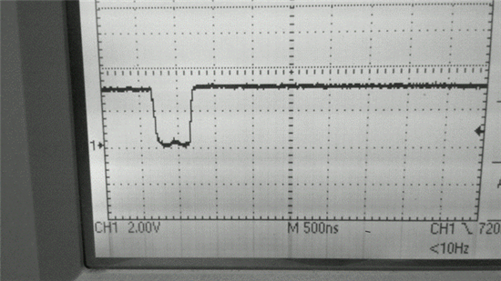
Although, The pin isn't generating interrupts as I'm expecting on the falling edge. My first try to fix the problem was to check if the IFR0, IER0 and INTM are configured correctly and They are.

IER0 = 0x0004; -> INT0 is enable.

INTM = 0; Global interruption is enable.

In other hand, my code had others interruptions and they are working properly. I took care to configure correctly the interrupt vector.

But I have realized that when I put the oscilloscope probe over the INT0 pin an interrupt event happens!  Someone have ideas to solve this issue? I 'm figuring out some hardware problem.......

Thanks for all!


Fred

PS: DSP TMS320C5502 -300 - CPU is running with 300 MHz


  • Hello Fred,

    Is this behavior seen on the C5502 EVM or on your custom board? If this is on the EVM, you could try using the INT1 or 2 interrupt to see if you see the same behavior.

    I suppose you use the same setup code (and steps) when trying to debug the INT0 interrupt as with the other interrupts.

    Do you see the INT0 flag set (without the probe on the pin)?

    Do you get the INT0 interrupt (with probe on pin) with other interrupts enabled?


    Regards,

    Sunil Kamath