This thread has been locked.

If you have a related question, please click the "Ask a related question" button in the top right corner. The newly created question will be automatically linked to this question.

TDA4VH-Q1: Evaluate 8 Eth ports of CPSW-9G on TDA4VH-EVM

Part Number: TDA4VH-Q1
Other Parts Discussed in Thread: TDA4VH

How to evaluate 8 Ethernet Port of CPSW-9G on TDA4VH EVM? Now can evaluate 4 port with 1 pcs of  J721EXENETXPANEVM.

#1. Can we use two pcs of  J721EXENETXPANEVM together to evaluate 8 ports? 

From the https://www.ti.com/lit/pdf/spruj74 user guide, support only one QP-ENET board. 

But on later page, two QP_ENET mounted. and has different EEPROM address.

Can we just change PHY address to difference of two ENET board to support 2 at the same time?

#2. I see another k3-j784s4-evm-usxgmii-exp1-exp2.dtso,which should be created for another extension board. but no more information for that.

  • Hi,

    How to evaluate 8 Ethernet Port of CPSW-9G on TDA4VH EVM? Now can evaluate 4 port with 1 pcs of  J721EXENETXPANEVM.

    #1. Can we use two pcs of  J721EXENETXPANEVM together to evaluate 8 ports? 

    Default 4 Ports only enabled as  J721EXENETXPANEVM required changes to have PHYs at different address.
    You can enable 8 Ports by connecting 2 Expansion connectors to EVM, also need to make sure the PHY address using in both should be different.

    From the https://www.ti.com/lit/pdf/spruj74 user guide, support only one QP-ENET board. 

    As it is ENT Expansion card User Guide, talks about single connector.

    But on later page, two QP_ENET mounted. and has different EEPROM address.

    As we have 8 Ports support from TDA4VH so 2 expansion connectors are connected and showing the same in User Guide.

    Can we just change PHY address to difference of two ENET board to support 2 at the same time?
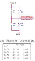
    Yes. Make sure both ENET Boards have different PHYs. you can connect and use both at the same time.

    #2. I see another k3-j784s4-evm-usxgmii-exp1-exp2.dtso,which should be created for another extension board. but no more information for that.

    It is for refence of how USXGMII to be configured. 

    TI internally validated in MAC to MAC connection by connecting two EVMs back to back using Bridge connector (which is TI internal purpose). There is no H/W connector support from TI for USXGMII.

    Best Regards,
    Sudheer

  • Hi Sudheer,

    Thanks.

    In order to support 2 ENET board for 8 port.

    #1. So need to change the PULL UP/DOWN resistor of  ENET PHY Address signal?

    #2. add another overlay dtso file to configure rest LVDS Lanes, is there a verified dtso for the second ENET board configuration?

  • Hi,

    #1. So need to change the PULL UP/DOWN resistor of  ENET PHY Address signal?

    Yes.

    #2. add another overlay dtso file to configure rest LVDS Lanes, is there a verified dtso for the second ENET board configuration?

    No need of another overlay add other CPSW Ports in the same overlay.
    Also, add PHY address in MDIO node.

    Along with above you need update POWER & RESET signals of ENET as below.

    For PHY reset add below in MDIO node reset-gpios.

    reset-gpios = <&exp2 17 GPIO_ACTIVE_LOW> , <&exp2 20 GPIO_ACTIVE_LOW>;


    For power on PHY add below in exp2 node:

    /* Power-up ENET2 EXPANDER PHY. */
    qsgmii1-line-hog {
        gpio-hog;
        gpios = <9 GPIO_ACTIVE_HIGH>;
        output-low;
    };

    Also, need to add SerDes2 lane for other ENET.
    As per TI EVM Port-7/Port-1 on Lane2 is available for ENET1 so either of one should be Master port.
    Port-8/Port-2 on Lane3 is available for ENET2 so either of one should be Master port.

    Among Port-1,2,3,4 one should be master and rest will be sub ports.
    Similarly among Port-5,6,7,8 one should be master and rest will be sub ports.

    Please use below for master ports defination

    &phy_gmii_sel_cpsw0 {
    ti,qsgmii-main-ports = <1>, <4>; //for Port1 & Port-8 Mater ports
    //ti,qsgmii-main-ports = <2>, <3>; //for Port2 & Port-7 Mater ports
    };


    Please use below Serdes Lane control  for IP selection as per master ports.
    &serdes_ln_ctrl {
    idle-states = <J784S4_SERDES0_LANE0_PCIE1_LANE0>, <J784S4_SERDES0_LANE1_PCIE1_LANE1>,
    <J784S4_SERDES0_LANE2_IP3_UNUSED>, <J784S4_SERDES0_LANE3_USB>,
    <J784S4_SERDES1_LANE0_PCIE0_LANE0>, <J784S4_SERDES1_LANE1_PCIE0_LANE1>,
    <J784S4_SERDES1_LANE2_PCIE0_LANE2>, <J784S4_SERDES1_LANE3_PCIE0_LANE3>,
    <J784S4_SERDES2_LANE0_QSGMII_LANE5>, <J784S4_SERDES2_LANE1_QSGMII_LANE6>,
    - <J784S4_SERDES2_LANE2_QSGMII_LANE7>, <J784S4_SERDES2_LANE3_QSGMII_LANE8>;
    + <J784S4_SERDES2_LANE2_QSGMII_LANE1>,<J784S4_SERDES2_LANE3_QSGMII_LANE8>; //for Port-1 Master and Port-8 Master
    //+ <J784S4_SERDES2_LANE2_QSGMII_LANE7>,<J784S4_SERDES2_LANE3_QSGMII_LANE2>; //for Port-2 Master and Port-7 Master
    };


    is there a verified dtso for the second ENET board configuration?

    No.

    Best Regards,
    Sudheer

  • Hi

      Board: TDA4VH

      SDK: 09.02.00.05(Linux kernel 6.18)

      I modified the k3-j784s4-evm-quad-port-eth-exp1.dtso file as described above. It is compiled and placed in the specified location and launched with uEnv.txt.

      "name_overlays=k3-j784s4-evm-virt-mac-client.dtbo k3-j784s4-vision-apps.dtbo k3-j784s4-evm-quad-port-eth-exp1.dtbo"   

      However, an error was reported during the startup process and the kernel could not be accessed.

    Load Remote Processor 10 with data@addr=0x82000000 14942480 bytes: Success!
    14942480 bytes read in 185 ms (77 MiB/s)
    Load Remote Processor 11 with data@addr=0x82000000 14942480 bytes: Success!
    19376640 bytes read in 227 ms (81.4 MiB/s)
    113787 bytes read in 30 ms (3.6 MiB/s)
    Working FDT set to 88000000
    3943 bytes read in 28 ms (136.7 KiB/s)
    14601 bytes read in 28 ms (508.8 KiB/s)
    4551 bytes read in 29 ms (152.3 KiB/s)
    failed on fdt_overlay_apply(): FDT_ERR_NOTFOUND
    ERROR: Did not find a cmdline Flattened Device Tree
    Could not find a valid device tree
    switch to partitions #0, OK
    mmc0(part 0) is current device
    ** No partition table - mmc 0 **
    Couldn't find partition mmc 0:1
    switch to partitions #0, OK
    mmc1 is current device
    Scanning mmc 1:1...
    No EFI system partition
    No EFI system partition
    Failed to persist EFI variables
    BootOrder not defined
    EFI boot manager: Cannot load any image
    starting USB...
    No working controllers found
    USB is stopped. Please issue 'usb start' first.
    starting USB...
    No working controllers found
    k3-navss-ringacc ringacc@2b800000: Ring Accelerator probed rings:286, gp-rings[96,20] sci-dev-id:328
    k3-navss-ringacc ringacc@2b800000: dma-ring-reset-quirk: disabled
    am65_cpsw_nuss_port ethernet@46000000port@1: K3 CPSW: rflow_id_base: 2
    link up on port 1, speed 1000, full duplex
    BOOTP broadcast 1
    BOOTP broadcast 2
    BOOTP broadcast 3
    BOOTP broadcast 4
    BOOTP broadcast 5
    BOOTP broadcast 6
    BOOTP broadcast 7
    BOOTP broadcast 8

      The modified dtso:

    #include <dt-bindings/gpio/gpio.h>
    #include <dt-bindings/mux/ti-serdes.h>
    #include <dt-bindings/phy/phy-cadence.h>
    #include <dt-bindings/phy/phy.h>
    
    #include "k3-pinctrl.h"
    
    &{/} {
    	aliases {
    		ethernet1 = "/bus@100000/ethernet@c000000/ethernet-ports/port@5";
    		ethernet2 = "/bus@100000/ethernet@c000000/ethernet-ports/port@6";
    		ethernet3 = "/bus@100000/ethernet@c000000/ethernet-ports/port@7";
    		ethernet4 = "/bus@100000/ethernet@c000000/ethernet-ports/port@8";
    	};
    };
    
    &main_cpsw0 {
    	status = "okay";
    };
    
    &main_cpsw0_port5 {
    	status = "okay";
    	phy-handle = <&cpsw9g_phy1>;
    	phy-mode = "qsgmii";
    	mac-address = [00 00 00 00 00 00];
    	phys = <&cpsw0_phy_gmii_sel 5>, <&serdes2_qsgmii_link>;
    	phy-names = "mac", "serdes";
    };
    
    &main_cpsw0_port6 {
    	status = "okay";
    	phy-handle = <&cpsw9g_phy2>;
    	phy-mode = "qsgmii";
    	mac-address = [00 00 00 00 00 00];
    	phys = <&cpsw0_phy_gmii_sel 6>, <&serdes2_qsgmii_link>;
    	phy-names = "mac", "serdes";
    };
    
    &main_cpsw0_port7 {
    	status = "okay";
    	phy-handle = <&cpsw9g_phy0>;
    	phy-mode = "qsgmii";
    	mac-address = [00 00 00 00 00 00];
    	phys = <&cpsw0_phy_gmii_sel 7>, <&serdes2_qsgmii_link>;
    	phy-names = "mac", "serdes";
    };
    
    &main_cpsw0_port8 {
    	status = "okay";
    	phy-handle = <&cpsw9g_phy3>;
    	phy-mode = "qsgmii";
    	mac-address = [00 00 00 00 00 00];
    	phys = <&cpsw0_phy_gmii_sel 8>, <&serdes2_qsgmii_link>;
    	phy-names = "mac", "serdes";
    };
    
    &main_cpsw0_mdio {
    	status = "okay";
    	pinctrl-names = "default";
    	pinctrl-0 = <&mdio0_pins_default>;
    	bus_freq = <1000000>;
    	reset-gpios = <&exp2 17 GPIO_ACTIVE_LOW>,<&exp2 20 GPIO_ACTIVE_LOW>;
    	reset-post-delay-us = <120000>;
    	#address-cells = <1>;
    	#size-cells = <0>;
    
    	cpsw9g_phy0: ethernet-phy@16 {
    		reg = <16>;
    	};
    	cpsw9g_phy1: ethernet-phy@17 {
    		reg = <17>;
    	};
    	cpsw9g_phy2: ethernet-phy@18 {
    		reg = <18>;
    	};
    	cpsw9g_phy3: ethernet-phy@19 {
    		reg = <19>;
    	};
    };
    
    &exp2 {
    	/* Power-up ENET1 EXPANDER PHY. */
    	qsgmii-line-hog {
    		gpio-hog;
    		gpios = <16 GPIO_ACTIVE_HIGH>;
    		output-low;
    	};
    	/* Power-up ENET2 EXPANDER PHY. */
    	qsgmii1-line-hog {
    		gpio-hog;
    		gpios = <9 GPIO_ACTIVE_HIGH>;
    		output-low;
    	};
    	/* Toggle MUX2 for MDIO lines */
    	mux-sel-hog {
    		gpio-hog;
    		gpios = <13 GPIO_ACTIVE_HIGH>, <14 GPIO_ACTIVE_HIGH>, <15 GPIO_ACTIVE_HIGH>;
    		output-high;
    	};
    };
    
    &phy_gmii_sel_cpsw0 {
    	ti,qsgmii-main-ports = <1>, <4>; //for Port1 & Port-8 Mater ports
    	//ti,qsgmii-main-ports = <2>, <3>; //for Port2 & Port-7 Mater ports
    };
    
    &main_pmx0 {
    	mdio0_pins_default: mdio0-pins-default {
    		pinctrl-single,pins = <
    			J784S4_IOPAD(0x05c, PIN_INPUT, 4) /* (AC36) MCASP2_AXR0.MDIO1_MDIO */
    			J784S4_IOPAD(0x058, PIN_INPUT, 4) /* (AE37) MCASP2_AFSX.MDIO1_MDC */
    		>;
    	};
    };
    
    &serdes_ln_ctrl {
    	idle-states = <J784S4_SERDES0_LANE0_PCIE1_LANE0>, <J784S4_SERDES0_LANE1_PCIE1_LANE1>,
    	<J784S4_SERDES0_LANE2_IP3_UNUSED>, <J784S4_SERDES0_LANE3_USB>,
    	<J784S4_SERDES1_LANE0_PCIE0_LANE0>, <J784S4_SERDES1_LANE1_PCIE0_LANE1>,
    	<J784S4_SERDES1_LANE2_PCIE0_LANE2>, <J784S4_SERDES1_LANE3_PCIE0_LANE3>,
    	<J784S4_SERDES2_LANE0_QSGMII_LANE5>, <J784S4_SERDES2_LANE1_QSGMII_LANE6>,
    	<J784S4_SERDES2_LANE2_QSGMII_LANE1>,<J784S4_SERDES2_LANE3_QSGMII_LANE8>; //for Port-1 Master and Port-8 Master
    };
    
    &serdes_wiz2 {
    	status = "okay";
    };
    
    &serdes2 {
    	status = "okay";
    	#address-cells = <1>;
    	#size-cells = <0>;
    
    	serdes2_qsgmii_link: phy@0 {
    		reg = <2>;
    		cdns,num-lanes = <1>;
    		#phy-cells = <0>;
    		cdns,phy-type = <PHY_TYPE_QSGMII>;
    		resets = <&serdes_wiz2 3>;
    	};
    };

      May I ask if there is any problem with this modification? Can you directly provide dtso or dtbo that supports eight network ports?

    Thanks,


  • Hi,

    Sorry for delay in response.
    Let me check the device tree files and get back to you soon.

    Best Regards,
    Sudheer

  • Hi,

    From modified device tree file, you are using only 4 Ports. For 4 Ports it is fine.
    You need to update for all 8 Ports.

    Out of which Port-1,2,3,4 are from ENET-1 Expansion and Port-1 will be Main Port and rest are SUB Ports.
    Similarly Port-8,5,6,7 are from ENET-2 Expansion and Port-8 will be Main Port and rest are SUB Ports.

    "name_overlays=k3-j784s4-evm-virt-mac-client.dtbo k3-j784s4-vision-apps.dtbo k3-j784s4-evm-quad-port-eth-exp1.dtbo"   

    In overlay ,remove virt-mac-client as you are planning to use Native Linux Driver with Quad eth expansion dtbo.

    Also, as you are using vision Apps, Please disable ETHFW from MCU2_0 and rebuild the vision application and use.

    Best Regards,
    Sudheer

  • Hi

      Now I can see port1-port8 through ifconfig. The four newly added ports have no signal.Could you please check the device tree for any problems.

    // SPDX-License-Identifier: GPL-2.0
    /**
     * DT Overlay for CPSW9G in QSGMII mode using J7 Quad Port ETH EXP Add-On Ethernet Card with
     * J7AHP board. The Add-On Ethernet Card has to be connected to ENET Expansion 1 slot on the
     * board.
     *
     * Product Datasheet: https://www.ti.com/lit/ug/spruj74/spruj74.pdf
     * Product Link: https://www.ti.com/tool/J721EXENETXPANEVM
     *
     * Copyright (C) 2023 Texas Instruments Incorporated - https://www.ti.com/
     */
    
    /dts-v1/;
    /plugin/;
    
    #include <dt-bindings/gpio/gpio.h>
    #include <dt-bindings/mux/ti-serdes.h>
    #include <dt-bindings/phy/phy-cadence.h>
    #include <dt-bindings/phy/phy.h>
    
    #include "k3-pinctrl.h"
    
    &{/} {
    	aliases {
    		ethernet1 = "/bus@100000/ethernet@c000000/ethernet-ports/port@5";
    		ethernet2 = "/bus@100000/ethernet@c000000/ethernet-ports/port@6";
    		ethernet3 = "/bus@100000/ethernet@c000000/ethernet-ports/port@7";
    		ethernet4 = "/bus@100000/ethernet@c000000/ethernet-ports/port@8";
    		ethernet5 = "/bus@100000/ethernet@c000000/ethernet-ports/port@1";
    		ethernet6 = "/bus@100000/ethernet@c000000/ethernet-ports/port@2";
    		ethernet7 = "/bus@100000/ethernet@c000000/ethernet-ports/port@3";
    		ethernet8 = "/bus@100000/ethernet@c000000/ethernet-ports/port@4";	
    	};
    };
    
    &main_cpsw0 {
    	status = "okay";
    };
    
    &main_cpsw0_port1 {
    	status = "okay";
    	phy-handle = <&cpsw9g_phy5>;
    	phy-mode = "qsgmii";
    	mac-address = [00 00 00 00 00 00];
    	phys = <&cpsw0_phy_gmii_sel 1>, <&serdes2_qsgmii_link>;
    	phy-names = "mac", "serdes";
    };
    
    &main_cpsw0_port2 {
    	status = "okay";
    	phy-handle = <&cpsw9g_phy6>;
    	phy-mode = "qsgmii";
    	mac-address = [00 00 00 00 00 00];
    	phys = <&cpsw0_phy_gmii_sel 2>, <&serdes2_qsgmii_link>;
    	phy-names = "mac", "serdes";
    };
    
    &main_cpsw0_port3 {
    	status = "okay";
    	phy-handle = <&cpsw9g_phy4>;
    	phy-mode = "qsgmii";
    	mac-address = [00 00 00 00 00 00];
    	phys = <&cpsw0_phy_gmii_sel 3>, <&serdes2_qsgmii_link>;
    	phy-names = "mac", "serdes";
    };
    
    &main_cpsw0_port4 {
    	status = "okay";
    	phy-handle = <&cpsw9g_phy7>;
    	phy-mode = "qsgmii";
    	mac-address = [00 00 00 00 00 00];
    	phys = <&cpsw0_phy_gmii_sel 4>, <&serdes2_qsgmii_link>;
    	phy-names = "mac", "serdes";
    };
    
    &main_cpsw0_port5 {
    	status = "okay";
    	phy-handle = <&cpsw9g_phy1>;
    	phy-mode = "qsgmii";
    	mac-address = [00 00 00 00 00 00];
    	phys = <&cpsw0_phy_gmii_sel 5>, <&serdes2_qsgmii_link>;
    	phy-names = "mac", "serdes";
    };
    
    &main_cpsw0_port6 {
    	status = "okay";
    	phy-handle = <&cpsw9g_phy2>;
    	phy-mode = "qsgmii";
    	mac-address = [00 00 00 00 00 00];
    	phys = <&cpsw0_phy_gmii_sel 6>, <&serdes2_qsgmii_link>;
    	phy-names = "mac", "serdes";
    };
    
    &main_cpsw0_port7 {
    	status = "okay";
    	phy-handle = <&cpsw9g_phy0>;
    	phy-mode = "qsgmii";
    	mac-address = [00 00 00 00 00 00];
    	phys = <&cpsw0_phy_gmii_sel 7>, <&serdes2_qsgmii_link>;
    	phy-names = "mac", "serdes";
    };
    
    &main_cpsw0_port8 {
    	status = "okay";
    	phy-handle = <&cpsw9g_phy3>;
    	phy-mode = "qsgmii";
    	mac-address = [00 00 00 00 00 00];
    	phys = <&cpsw0_phy_gmii_sel 8>, <&serdes2_qsgmii_link>;
    	phy-names = "mac", "serdes";
    };
    
    
    &cpsw0_phy_gmii_sel {
    	ti,qsgmii-main-ports = <1>, <4>; //for Port1 & Port-8 Mater ports
    };
    
    &main_cpsw0_mdio {
    	status = "okay";
    	pinctrl-names = "default";
    	pinctrl-0 = <&mdio0_pins_default>;
    	bus_freq = <1000000>;
    	reset-gpios = <&exp2 17 GPIO_ACTIVE_LOW>,<&exp2 20 GPIO_ACTIVE_LOW>;
    	reset-post-delay-us = <120000>;
    	#address-cells = <1>;
    	#size-cells = <0>;
    
    	cpsw9g_phy0: ethernet-phy@16 {
    		reg = <16>;
    	};
    	cpsw9g_phy1: ethernet-phy@17 {
    		reg = <17>;
    	};
    	cpsw9g_phy2: ethernet-phy@18 {
    		reg = <18>;
    	};
    	cpsw9g_phy3: ethernet-phy@19 {
    		reg = <19>;
    	};
    	cpsw9g_phy4: ethernet-phy@20 {
    		reg = <20>;
    	};
    	cpsw9g_phy5: ethernet-phy@21 {
    		reg = <21>;
    	};
    	cpsw9g_phy6: ethernet-phy@22 {
    		reg = <22>;
    	};
    	cpsw9g_phy7: ethernet-phy@23 {
    		reg = <23>;
    	};
    };
    
    &exp2 {
    	/* Power-up ENET1 EXPANDER PHY. */
    	qsgmii-line-hog {
    		gpio-hog;
    		gpios = <16 GPIO_ACTIVE_HIGH>;
    		output-low;
    	};
    	/* Power-up ENET2 EXPANDER PHY. */
    	qsgmii1-line-hog {
    		gpio-hog;
    		gpios = <9 GPIO_ACTIVE_HIGH>;
    		output-low;
    	};
    	/* Toggle MUX2 for MDIO lines */
    	mux-sel-hog {
    		gpio-hog;
    		gpios = <13 GPIO_ACTIVE_HIGH>, <14 GPIO_ACTIVE_HIGH>, <15 GPIO_ACTIVE_HIGH>;
    		output-high;
    	};
    };
    
    &main_pmx0 {
    	mdio0_pins_default: mdio0-pins-default {
    		pinctrl-single,pins = <
    			J784S4_IOPAD(0x05c, PIN_INPUT, 4) /* (AC36) MCASP2_AXR0.MDIO1_MDIO */
    			J784S4_IOPAD(0x058, PIN_INPUT, 4) /* (AE37) MCASP2_AFSX.MDIO1_MDC */
    		>;
    	};
    };
    
    &serdes_ln_ctrl {
    	idle-states = <J784S4_SERDES0_LANE0_PCIE1_LANE0>, <J784S4_SERDES0_LANE1_PCIE1_LANE1>,
    	<J784S4_SERDES0_LANE2_IP3_UNUSED>, <J784S4_SERDES0_LANE3_USB>,
    	<J784S4_SERDES1_LANE0_PCIE0_LANE0>, <J784S4_SERDES1_LANE1_PCIE0_LANE1>,
    	<J784S4_SERDES1_LANE2_PCIE0_LANE2>, <J784S4_SERDES1_LANE3_PCIE0_LANE3>,
    	<J784S4_SERDES2_LANE0_QSGMII_LANE5>, <J784S4_SERDES2_LANE1_QSGMII_LANE6>,
    	<J784S4_SERDES2_LANE2_QSGMII_LANE1>,<J784S4_SERDES2_LANE3_QSGMII_LANE8>; //for Port-1 Master and Port-8 Master
    };
    
    &serdes_wiz2 {
    	status = "okay";
    };
    
    &serdes2 {
    	status = "okay";
    	#address-cells = <1>;
    	#size-cells = <0>;
    
    	serdes2_qsgmii_link: phy@0 {
    		reg = <2>;
    		cdns,num-lanes = <1>;
    		#phy-cells = <0>;
    		cdns,phy-type = <PHY_TYPE_QSGMII>;
    		resets = <&serdes_wiz2 3>;
    	};
    };
    

    If you want me to configure the other four network ports separately, may I ask what pin to configure the &serdes_ln_ctrl and &main_pmx0 nodes?

  • Hi

    What do you mean by no signal, is it no LED on EXP-1 connector?

    I could see you are enabling only one SerDes Line i.e. Line 2 from SerDes2 which enables Port-1 as Master and 2,3,4 as Sub Ports.
    You need to configure SerDes to enable both Line2 (Port-1), Line3(Port-8), It should be as follows.

    &serdes2 {
    	status = "okay";
    	#address-cells = <1>;
    	#size-cells = <0>;
    
    	serdes2_qsgmii_link: phy@0 {
    		reg = <2>;
    		cdns,num-lanes = <2>;
    		#phy-cells = <0>;
    		cdns,phy-type = <PHY_TYPE_QSGMII>;
    		resets = <&serdes_wiz2 3>, <&serdes_wiz2 4>;
    	};
    };

    &serdes_ln_ctrl

    Here, we have already configured SerDes2 Line2, Line3 for Ethernet functionality.

    &main_pmx0 nodes?

    No need to configure Main Pinmux for SerDes Pins.


    Best Regards,
    Sudheer

  • Hi,

      We modified the &serdes_ln_ctrl node according to your description.We also found that the physical address of cpsw9g_phy4-cpsw9g_phy7 was incorrect, so we also changed it. After making these changes, the board can load eth1-eth8. But I  can't ping my computer after setting the IP(eth1-eth8).

      The original device tree can make the first four network ports to work properly. The modified device tree can load eight network ports, but none of them can be used normally.

    The device tree:

    // SPDX-License-Identifier: GPL-2.0
    /**
     * DT Overlay for CPSW9G in QSGMII mode using J7 Quad Port ETH EXP Add-On Ethernet Card with
     * J7AHP board. The Add-On Ethernet Card has to be connected to ENET Expansion 1 slot on the
     * board.
     *
     * Product Datasheet: https://www.ti.com/lit/ug/spruj74/spruj74.pdf
     * Product Link: https://www.ti.com/tool/J721EXENETXPANEVM
     *
     * Copyright (C) 2023 Texas Instruments Incorporated - https://www.ti.com/
     */
    
    /dts-v1/;
    /plugin/;
    
    #include <dt-bindings/gpio/gpio.h>
    #include <dt-bindings/mux/ti-serdes.h>
    #include <dt-bindings/phy/phy-cadence.h>
    #include <dt-bindings/phy/phy.h>
    
    #include "k3-pinctrl.h"
    
    &{/} {
    	aliases {
    		ethernet1 = "/bus@100000/ethernet@c000000/ethernet-ports/port@5";
    		ethernet2 = "/bus@100000/ethernet@c000000/ethernet-ports/port@6";
    		ethernet3 = "/bus@100000/ethernet@c000000/ethernet-ports/port@7";
    		ethernet4 = "/bus@100000/ethernet@c000000/ethernet-ports/port@8";
    		ethernet5 = "/bus@100000/ethernet@c000000/ethernet-ports/port@1";
    		ethernet6 = "/bus@100000/ethernet@c000000/ethernet-ports/port@2";
    		ethernet7 = "/bus@100000/ethernet@c000000/ethernet-ports/port@3";
    		ethernet8 = "/bus@100000/ethernet@c000000/ethernet-ports/port@4";	
    	};
    };
    
    &main_cpsw0 {
    	status = "okay";
    };
    
    &main_cpsw0_port1 {
    	status = "okay";
    	phy-handle = <&cpsw9g_phy5>;
    	phy-mode = "qsgmii";
    	mac-address = [00 00 00 00 00 00];
    	phys = <&cpsw0_phy_gmii_sel 1>, <&serdes2_qsgmii_link>;
    	phy-names = "mac", "serdes";
    };
    
    &main_cpsw0_port2 {
    	status = "okay";
    	phy-handle = <&cpsw9g_phy6>;
    	phy-mode = "qsgmii";
    	mac-address = [00 00 00 00 00 00];
    	phys = <&cpsw0_phy_gmii_sel 2>, <&serdes2_qsgmii_link>;
    	phy-names = "mac", "serdes";
    };
    
    &main_cpsw0_port3 {
    	status = "okay";
    	phy-handle = <&cpsw9g_phy4>;
    	phy-mode = "qsgmii";
    	mac-address = [00 00 00 00 00 00];
    	phys = <&cpsw0_phy_gmii_sel 3>, <&serdes2_qsgmii_link>;
    	phy-names = "mac", "serdes";
    };
    
    &main_cpsw0_port4 {
    	status = "okay";
    	phy-handle = <&cpsw9g_phy7>;
    	phy-mode = "qsgmii";
    	mac-address = [00 00 00 00 00 00];
    	phys = <&cpsw0_phy_gmii_sel 4>, <&serdes2_qsgmii_link>;
    	phy-names = "mac", "serdes";
    };
    
    &main_cpsw0_port5 {
    	status = "okay";
    	phy-handle = <&cpsw9g_phy1>;
    	phy-mode = "qsgmii";
    	mac-address = [00 00 00 00 00 00];
    	phys = <&cpsw0_phy_gmii_sel 5>, <&serdes2_qsgmii_link>;
    	phy-names = "mac", "serdes";
    };
    
    &main_cpsw0_port6 {
    	status = "okay";
    	phy-handle = <&cpsw9g_phy2>;
    	phy-mode = "qsgmii";
    	mac-address = [00 00 00 00 00 00];
    	phys = <&cpsw0_phy_gmii_sel 6>, <&serdes2_qsgmii_link>;
    	phy-names = "mac", "serdes";
    };
    
    &main_cpsw0_port7 {
    	status = "okay";
    	phy-handle = <&cpsw9g_phy0>;
    	phy-mode = "qsgmii";
    	mac-address = [00 00 00 00 00 00];
    	phys = <&cpsw0_phy_gmii_sel 7>, <&serdes2_qsgmii_link>;
    	phy-names = "mac", "serdes";
    };
    
    &main_cpsw0_port8 {
    	status = "okay";
    	phy-handle = <&cpsw9g_phy3>;
    	phy-mode = "qsgmii";
    	mac-address = [00 00 00 00 00 00];
    	phys = <&cpsw0_phy_gmii_sel 8>, <&serdes2_qsgmii_link>;
    	phy-names = "mac", "serdes";
    };
    
    
    &cpsw0_phy_gmii_sel {
    	ti,qsgmii-main-ports = <1>, <4>; //for Port1 & Port-8 Mater ports
    };
    
    &main_cpsw0_mdio {
    	status = "okay";
    	pinctrl-names = "default";
    	pinctrl-0 = <&mdio0_pins_default>;
    	bus_freq = <1000000>;
    	reset-gpios = <&exp2 20 GPIO_ACTIVE_LOW>, <&exp2 17 GPIO_ACTIVE_LOW>;
    	reset-post-delay-us = <120000>;
    	#address-cells = <1>;
    	#size-cells = <0>;
    
    	cpsw9g_phy0: ethernet-phy@16 {
    		reg = <16>;
    	};
    	cpsw9g_phy1: ethernet-phy@17 {
    		reg = <17>;
    	};
    	cpsw9g_phy2: ethernet-phy@18 {
    		reg = <18>;
    	};
    	cpsw9g_phy3: ethernet-phy@19 {
    		reg = <19>;
    	};
    	cpsw9g_phy4: ethernet-phy@24 {
    		reg = <24>;
    	};
    	cpsw9g_phy5: ethernet-phy@25 {
    		reg = <25>;
    	};
    	cpsw9g_phy6: ethernet-phy@26 {
    		reg = <26>;
    	};
    	cpsw9g_phy7: ethernet-phy@27 {
    		reg = <27>;
    	};
    };
    
    &exp2 {
    	/* Power-up ENET1 EXPANDER PHY. */
    	qsgmii1-line-hog {
    		gpio-hog;
    		gpios = <9 GPIO_ACTIVE_HIGH>;
    		output-low;
    	};
    	/* Power-up ENET1 EXPANDER PHY. */
    	qsgmii-line-hog {
    		gpio-hog;
    		gpios = <16 GPIO_ACTIVE_HIGH>;
    		output-low;
    	};
    	/* Toggle MUX2 for MDIO lines */
    	mux-sel-hog {
    		gpio-hog;
    		gpios = <13 GPIO_ACTIVE_HIGH>, <14 GPIO_ACTIVE_HIGH>, <15 GPIO_ACTIVE_HIGH>;
    		output-high;
    	};
    };
    
    &main_pmx0 {
    	mdio0_pins_default: mdio0-pins-default {
    		pinctrl-single,pins = <
    			J784S4_IOPAD(0x05c, PIN_INPUT, 4) /* (AC36) MCASP2_AXR0.MDIO1_MDIO */
    			J784S4_IOPAD(0x058, PIN_INPUT, 4) /* (AE37) MCASP2_AFSX.MDIO1_MDC */
    		>;
    	};
    };
    
    &serdes_ln_ctrl {
    	idle-states = <J784S4_SERDES0_LANE0_PCIE1_LANE0>, <J784S4_SERDES0_LANE1_PCIE1_LANE1>,
    	<J784S4_SERDES0_LANE2_IP3_UNUSED>, <J784S4_SERDES0_LANE3_USB>,
    	<J784S4_SERDES1_LANE0_PCIE0_LANE0>, <J784S4_SERDES1_LANE1_PCIE0_LANE1>,
    	<J784S4_SERDES1_LANE2_PCIE0_LANE2>, <J784S4_SERDES1_LANE3_PCIE0_LANE3>,
    	<J784S4_SERDES2_LANE0_QSGMII_LANE5>, <J784S4_SERDES2_LANE1_QSGMII_LANE6>,
    	<J784S4_SERDES2_LANE2_QSGMII_LANE1>,<J784S4_SERDES2_LANE3_QSGMII_LANE8>; //for Port-1 Master and Port-8 Master
    };
    
    &serdes_wiz2 {
    	status = "okay";
    };
    
    &serdes2 {
    	status = "okay";
    	#address-cells = <1>;
    	#size-cells = <0>;
    
    	serdes2_qsgmii_link: phy@0 {
    		reg = <2>;
    		cdns,num-lanes = <2>;
    		#phy-cells = <0>;
    		cdns,phy-type = <PHY_TYPE_QSGMII>;
    		resets = <&serdes_wiz2 3>, <&serdes_wiz2 4>;
    	};
    };
    

    &main_cpsw0_port1 {
          status = "okay";
          phy-handle = <&cpsw9g_phy5>;
          phy-mode = "qsgmii";
          mac-address = [00 00 00 00 00 00];
          phys = <&cpsw0_phy_gmii_sel 1>, <&serdes2_qsgmii_link>;
          phy-names = "mac", "serdes";
    }; 

    &cpsw0_phy_gmii_sel {
         ti,qsgmii-main-ports = <1>, <4>; //for Port1 & Port-8 Mater ports
    };

    &serdes_ln_ctrl {
    idle-states = <J784S4_SERDES0_LANE0_PCIE1_LANE0>, <J784S4_SERDES0_LANE1_PCIE1_LANE1>,
       <J784S4_SERDES0_LANE2_IP3_UNUSED>, <J784S4_SERDES0_LANE3_USB>,
       <J784S4_SERDES1_LANE0_PCIE0_LANE0>, <J784S4_SERDES1_LANE1_PCIE0_LANE1>,
       <J784S4_SERDES1_LANE2_PCIE0_LANE2>, <J784S4_SERDES1_LANE3_PCIE0_LANE3>,
       <J784S4_SERDES2_LANE0_QSGMII_LANE5>, <J784S4_SERDES2_LANE1_QSGMII_LANE6>,
       <J784S4_SERDES2_LANE2_QSGMII_LANE1>,<J784S4_SERDES2_LANE3_QSGMII_LANE8>; //for Port-1 Master and Port-8 Master
    };

      Are these yellow spots incorrectly configured? In your reply above, does the &phy_gmii_sel_cpsw0 node mean &cpsw0_phy_gmii_sel node?(I added the &phy_gmii_sel_cpsw0 node and the board crashed)

    Thanks,

  • Hi,

    Are these yellow spots incorrectly configured? In your reply above, does the &phy_gmii_sel_cpsw0 node mean &cpsw0_phy_gmii_sel node?(I added the &phy_gmii_sel_cpsw0 node and the board crashed)

    Yes, phy_gmii_sel_cpsw0 in above is "cpsw0_phy_gmii_sel". I might have shared from previous SDK versions.

    Also, make sure that the Expansion connector connected to EVM's ENET-1 and ENET-2 as below.

    ENET-1 to the QUAD Expansion without H/W changes.
    ENET-2 with updated PHY addresses.

    Best Regards,
    Sudheer

  • Hi,

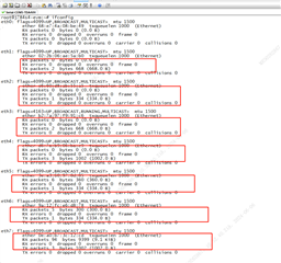
      The hardware connection is correct. The eight network ports are loaded out, but after inserting the network cable, Tx has data, Rx has no data.

      Hardware address configuration:

        ENET-1:0x10 0x11 0x12 0x13

        ENET-2:0x18 0x19 0x1a 0x1b

      Software  &main_cpsw0_mdio configuration:


    &main_cpsw0_mdio {
    	status = "okay";
    	pinctrl-names = "default";
    	pinctrl-0 = <&mdio0_pins_default>;
    	bus_freq = <1000000>;
    	reset-gpios = <&exp2 20 GPIO_ACTIVE_LOW>, <&exp2 17 GPIO_ACTIVE_LOW>;
    	reset-post-delay-us = <120000>;
    	#address-cells = <1>;
    	#size-cells = <0>;
    
    	cpsw9g_phy0: ethernet-phy@16 {
    		reg = <16>;
    	};
    	cpsw9g_phy1: ethernet-phy@17 {
    		reg = <17>;
    	};
    	cpsw9g_phy2: ethernet-phy@18 {
    		reg = <18>;
    	};
    	cpsw9g_phy3: ethernet-phy@19 {
    		reg = <19>;
    	};
    	cpsw9g_phy4: ethernet-phy@24 {
    		reg = <24>;
    	};
    	cpsw9g_phy5: ethernet-phy@25 {
    		reg = <25>;
    	};
    	cpsw9g_phy6: ethernet-phy@26 {
    		reg = <26>;
    	};
    	cpsw9g_phy7: ethernet-phy@27 {
    		reg = <27>;
    	};
    };

      I modified the binding relationship between &main_cpsw0_port* and &cpsw9g_phy* and found that the four ports of ENET-1 can be used normally. Then ENET-2's four ports still only have Tx data.

    &main_cpsw0_port1 {
    	status = "okay";
    	phy-handle = <&cpsw9g_phy0>;
    	phy-mode = "qsgmii";
    	mac-address = [00 00 00 00 00 00];
    	phys = <&cpsw0_phy_gmii_sel 1>, <&serdes2_qsgmii_link>;
    	phy-names = "mac", "serdes";
    };
    
    &main_cpsw0_port2 {
    	status = "okay";
    	phy-handle = <&cpsw9g_phy1>;
    	phy-mode = "qsgmii";
    	mac-address = [00 00 00 00 00 00];
    	phys = <&cpsw0_phy_gmii_sel 2>, <&serdes2_qsgmii_link>;
    	phy-names = "mac", "serdes";
    };
    
    &main_cpsw0_port3 {
    	status = "okay";
    	phy-handle = <&cpsw9g_phy2>;
    	phy-mode = "qsgmii";
    	mac-address = [00 00 00 00 00 00];
    	phys = <&cpsw0_phy_gmii_sel 3>, <&serdes2_qsgmii_link>;
    	phy-names = "mac", "serdes";
    };
    
    &main_cpsw0_port4 {
    	status = "okay";
    	phy-handle = <&cpsw9g_phy4>;
    	phy-mode = "qsgmii";
    	mac-address = [00 00 00 00 00 00];
    	phys = <&cpsw0_phy_gmii_sel 4>, <&serdes2_qsgmii_link>;
    	phy-names = "mac", "serdes";
    };
    
    &main_cpsw0_port5 {
    	status = "okay";
    	phy-handle = <&cpsw9g_phy3>;
    	phy-mode = "qsgmii";
    	mac-address = [00 00 00 00 00 00];
    	phys = <&cpsw0_phy_gmii_sel 5>, <&serdes2_qsgmii_link>;
    	phy-names = "mac", "serdes";
    };
    
    &main_cpsw0_port6 {
    	status = "okay";
    	phy-handle = <&cpsw9g_phy5>;
    	phy-mode = "qsgmii";
    	mac-address = [00 00 00 00 00 00];
    	phys = <&cpsw0_phy_gmii_sel 6>, <&serdes2_qsgmii_link>;
    	phy-names = "mac", "serdes";
    };
    
    &main_cpsw0_port7 {
    	status = "okay";
    	phy-handle = <&cpsw9g_phy6>;
    	phy-mode = "qsgmii";
    	mac-address = [00 00 00 00 00 00];
    	phys = <&cpsw0_phy_gmii_sel 7>, <&serdes2_qsgmii_link>;
    	phy-names = "mac", "serdes";
    };
    
    &main_cpsw0_port8 {
    	status = "okay";
    	phy-handle = <&cpsw9g_phy7>;
    	phy-mode = "qsgmii";
    	mac-address = [00 00 00 00 00 00];
    	phys = <&cpsw0_phy_gmii_sel 8>, <&serdes2_qsgmii_link>;
    	phy-names = "mac", "serdes";
    };

     I want to know what this &cpsw0_phy_gmii_sel node does and whether this configuration is related to the binding relationship between the two nodes above.I don't know how the source code is parsed, so I'm confused here. Qsgmi-main-ports is set to 1 and 4. What is the correspondence between &main_cpsw0_port* and &cpsw9g_phy*? I guess my mapping is wrong.(I tried a variety of other groups and ENET-2 did not work properly,The &cpsw9g_phy3 node cannot be placed on the &main_cpsw0_port4 node. Otherwise, one of the ENET-1 ports can be used properly.)

    &cpsw0_phy_gmii_sel {
        ti,qsgmii-main-ports = <1>, <4>; //for Port1 & Port-8 Mater ports
    };

    Thanks, 


  • Hi,

      Could you please reply to yesterday's question?

    Thanks,

  • Hi, 

    Will be OoO today, will check in some time tomorrow. 

    Best regards, 

    Sudheer

  • Hi,

      Try to debug ENET-2 separately. The same phenomenon occurs as before, Tx has data Rx has no data.If I want to use the four network ports of ENET-2 separately, how to modify the k3-j784s4-evm-quad-port-eth-exp1.dtso. Where can I find detailed documentation for cpsw9g?

    Thanks,

  • Hi,

      The hardware connection is correct. The eight network ports are loaded out, but after inserting the network cable, Tx has data, Rx has no data.


      What does the value 7 in phys = <&cpsw0_phy_gmii_sel 7>  mean? How does this relate to the ti,qsgmii-main-ports attribute?

    Thanks, 


  • What does the value 7 in phys = <&cpsw0_phy_gmii_sel 7>  mean? How does this relate to the ti,qsgmii-main-ports attribute?

    cpsw0_phy_gmii_sel will pass Port number 7 as qsgmii.
    ti,qsgmii-main-ports -> will define which are Master ports among all QSGMII Ports.

    We have enabled Port-1, Port-8 as Master Ports.

    From capture it seems, you are not receiving the data on eth1, eth2, eth3, eth4 and receiving on eth5, eth6, eth7 and eth8?

    Can you please check with below main port configuration once.
    &cpsw0_phy_gmii_sel {
        ti,qsgmii-main-ports = <1>, <8>; //for Port1 & Port-8 Mater ports
    };

    Best Regards,
    Sudheer

  • Hi 

      Yes, using the main port <1,8>, the eight network ports are already working properly. Our hardware engineer asked the rereset -gpios in &main_cpsw0_mdio node is used for? How do you determine the values of 17 and 20?

      After specifying the main port(1,8), I found that the other three cpsw0_phy_gmii_sel xx also had a one-to-one relationship with the actual physical port. What determines this relationship? 

    Thanks,

  • Hi,

    How do you determine the values of 17 and 20?

    This is from the Schematic, we have GPIO hogs for the reset of Expansion connector.

    After specifying the main port(1,8), I found that the other three cpsw0_phy_gmii_sel xx also had a one-to-one relationship with the actual physical port. What determines this relationship

    Here, Port-1 will act as Master and reset 3 from starting Ports i.e. Port-2, Port-3, Port-4 are sub Ports of Main Port-1.

    Similarly, Port-8 is Master and reset 3 from remaining i.e. Port-5, Port-6, Port-7 are sub ports of Main Port-8.

    Above is H/W behavior for grouping sub ports to Main Ports.


    I understand your issue is resolved after configuring main ports <1>,<8>

    Best Regards.
    Sudheer