Because of the holidays, TI E2E™ design support forum responses will be delayed from Dec. 25 through Jan. 2. Thank you for your patience.

This thread has been locked.

If you have a related question, please click the "Ask a related question" button in the top right corner. The newly created question will be automatically linked to this question.

RE: PROCESSOR-SDK-AM62X: M4F Main Domain UART errors

Other Parts Discussed in Thread: SYSCONFIG

Hi Nick,

By referring to below example, we are able to poll the UART RX for main domain UART using 100us timer.

software-dl.ti.com/.../EXAMPLES_DRIVERS_UART_ECHO_LOW_LATENCY_POLLING.html

I am aware there is no interrupt routed to M4F core for main domain UART.

software-dl.ti.com/.../MAIN_DOMAIN_PERIPHERAL_FROM_MCU.html

But, how about the RX error status for main domain UART ??? In some test cases, I expected an overrun error, but the code below does not seem to flag that.

Also, shouldn't be the "Read and throw Erroneous bytes from RxFIFO" code block checks for "while (0 != errorVal)" instead of checking the errorVal with all the error bits set ???

/mcu_plus_sdk_am62x_09_02_00_38/source/drivers/uart/v0/uart.h

static inline uint8_t UART_getCharFifo(uint32_t baseAddr, uint8_t *readBuf)
{
    uint8_t           readByte = 0;
    uint32_t          waitCount = UART_ERROR_COUNT;
    uint32_t          errorVal;
    uint32_t          lcrRegValue = 0;

    /* Preserving the current value of LCR. */
    lcrRegValue = HW_RD_REG32(baseAddr + UART_LCR);

    /* Switching to Register Operational Mode of operation. */
    HW_WR_REG32(baseAddr + UART_LCR, HW_RD_REG32(baseAddr + UART_LCR)
                            & 0x7FU);

    /* Read Rx Error Status */
    errorVal = HW_RD_REG32(baseAddr + UART_LSR) &
             (UART_LSR_RX_FIFO_STS_MASK |
              UART_LSR_RX_BI_MASK |
              UART_LSR_RX_FE_MASK |
              UART_LSR_RX_PE_MASK |
              UART_LSR_RX_OE_MASK);

    /* Restoring the value of LCR. */
    HW_WR_REG32(baseAddr + UART_LCR, lcrRegValue);

    /* Read and throw Erroneous bytes from RxFIFO */
    while ((UART_LSR_RX_FIFO_STS_MASK |
            UART_LSR_RX_BI_MASK |
            UART_LSR_RX_FE_MASK |
            UART_LSR_RX_PE_MASK |
            UART_LSR_RX_OE_MASK) == errorVal)
    {
        readByte = (uint8_t) (HW_RD_REG32(baseAddr + UART_RHR) & 0xFFU);
        waitCount--;
        if (0U == waitCount)
        {
            break;
        }

        /* Preserving the current value of LCR. */
        lcrRegValue = HW_RD_REG32(baseAddr + UART_LCR);

        /* Switching to Register Operational Mode of operation. */
        HW_WR_REG32(baseAddr + UART_LCR, HW_RD_REG32(baseAddr + UART_LCR)
                                & 0x7FU);

        /* Read Rx Error Status */
        errorVal = HW_RD_REG32(baseAddr + UART_LSR) &
                 (UART_LSR_RX_FIFO_STS_MASK |
                  UART_LSR_RX_BI_MASK |
                  UART_LSR_RX_FE_MASK |
                  UART_LSR_RX_PE_MASK |
                  UART_LSR_RX_OE_MASK);

        /* Restoring the value of LCR. */
        HW_WR_REG32(baseAddr + UART_LCR, lcrRegValue);
    }

    /* Read non-erroneous byte from RxFIFO */
    readByte = (uint8_t) (HW_RD_REG32(baseAddr + UART_RHR) & 0xFFU);

    return readByte;
}

rgds,

kc Wong

  • Hello KC Wong,

    I have split your UART question into a separate thread, and I am reassigning it to another team member who is more familiar with the MCU+ UART driver. Please ping the thread if you do not get a response within a couple of business days.

    Regards,

    Nick

  • OK, thanks Nick.

    Also, I am looking for API to change the UART buad rate, but did not find one.

    software-dl.ti.com/.../group__DRV__UART__MODULE.html

    Our application is required to support different baud rate configuration. How to change the UART buad rate in M4F core application ?


    rgds,

    kc Wong

  • Hello Kiung,

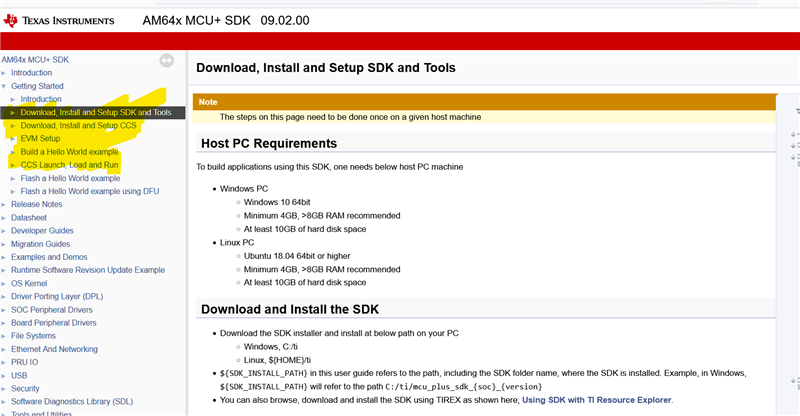
    Your development will be smooth and we can support better, if you can follow this workflow: https://software-dl.ti.com/mcu-plus-sdk/esd/AM64X/09_02_00_50/exports/docs/api_guide_am64x/SDK_DOWNLOAD_PAGE.html

    If you follow the flow, then you will gradually end up learning how to import examples into a IDE like Code Composer Studio.

    From here onwards, you can reap the benefits of SysConfig.

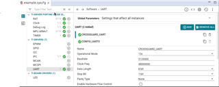
    Here in SysConfig you can configure most of the settings with respect to different peripherals.

    I am saying all of this as one of your subquestions is "How to change the baud rate of UART?"

    Regards,

    Vaibhav

  • Sorry, I accidentally pressed the "This resolved my issue" button. I found no way to undo that.

    We are indeed following the steps that your suggested for the development.


    And we have our initial baud rate set using the SysConfig tool in the CCS.

    But, we need the baud rate to change at run time and not fixed to this initial baud rate for all the use cases.

    Also, can we change the Clock Freq to 50000000 instead of the default 48000000 ???

    It is because some of the baud rates that we need has less error with 50MHz clock frequency.

  • Hi Kiung,

    I would suggest to not change the UART baud rate on the go, as this might result in unambiguity down the line when your production code grows.

    But if you are interested to do so, I think the best way to do would be by having a gap of lets say 30 seconds, between your last UART write or Read operation and then you can wait for 30 seconds and enter the new baud rate(as its dynamic). If you do not enter the new baud rate in 30 seconds, then the timer has expired and the operation would happen at the original baud rate. If you give the input, the new baud rate will be applied.

    This is what I would have preferred to do if I had a use case of Dynamic UART Baud Rate.

    Well, currently there is no API which does so, but you can create one. 

    I am currently browsing through TRM and will help you by seeing which register is responsible for baud rate.

    Please allow me sometime on this.

    Regards,

    Vaibhav

  • Greetings Kiung,

    Apologies in delayed responses as I was out of office.

    Lets take this step by step.

    Before rushing and knowing how to change the baud rate, let's look at how the baud rate is computed ( the most important factor)

    So, we need three values in order to compute the baud rate, they are as follows:

    1. Source Clock
    2. Divisor value
    3. Operational mode value

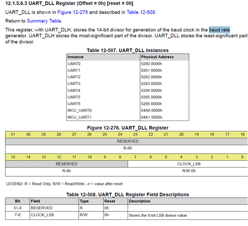
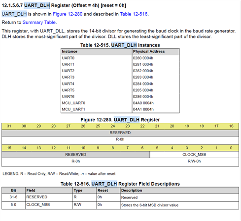
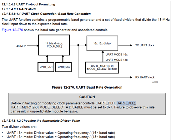
    The divisor value is a 14 bit value hence it is divided into two registers namely, UART_DLH and UART_DLL registers, I highly recommend you to look at these two registers in the TRM, anyhow I am attaching it here as well.

    Important


    The following diagram shows how the baud rate is computed along with the formula mentioned at the bottom of the image.

    Currently, by default the Divisor value is 26 and the operational mode value is 16x, so total baud rate comes out to be(considering the functional operating frequency as 48 MHz):

    Baud Rate = 48000000 / (16 * 26) = approx 115200

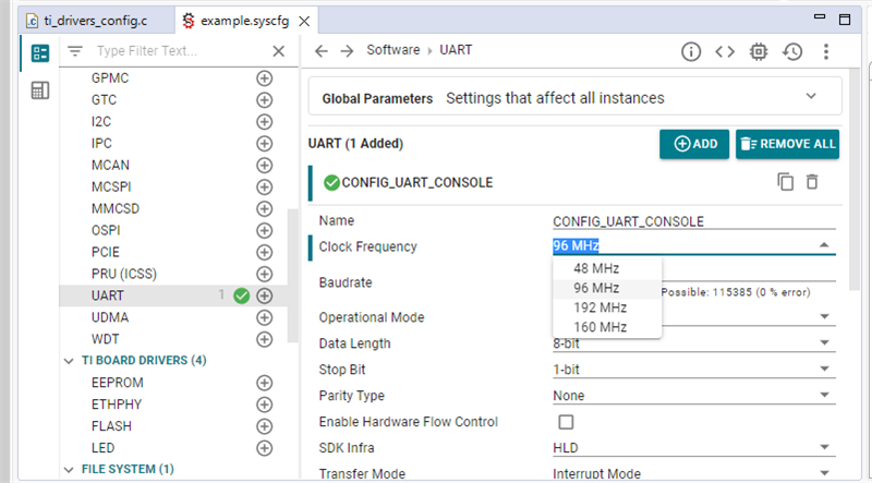
    Now if you want to change the baud rate you need to change the frequency, all from SysConfig itself.

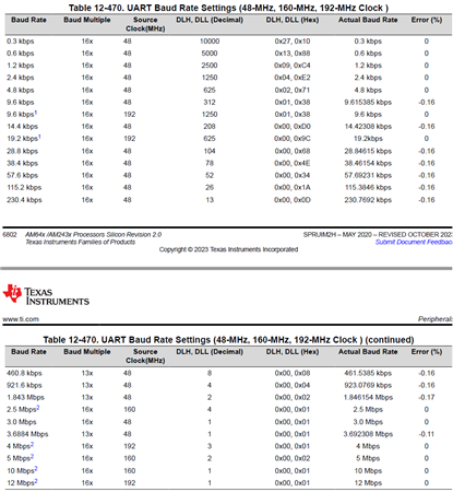
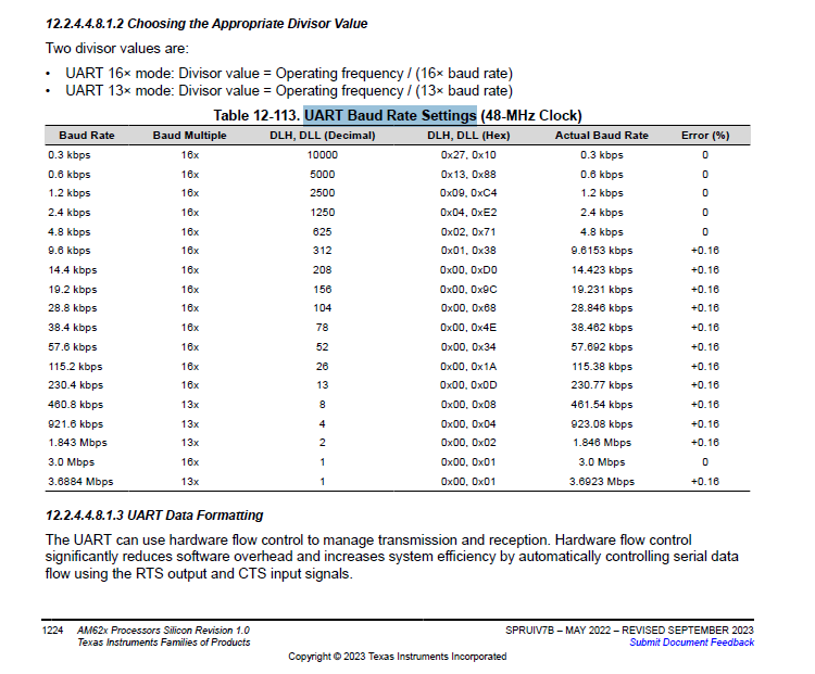
    For different supported combinations I would request you to look at the table from TRM.

    Based on the table, you can change the UART_DLH and UART_DLL values to be able to get the desired baud rate.

    I hope this clarifies your doubts on how to change the baud rate.

    Regards,

    Vaibhav

  • Hi Vaibhav,

    Thanks for the info. I am actually aware of those registers and that formula from spruiv7b reference manual.

    I am currently using the UART_close() and UART_open() APIs whenever there is a need to change the baud rate.

    AM62x MCU+ SDK: APIs for UART (ti.com)

    bool Uart::SetBaudRate(uint32_t baudrate)
    {
        switch (baudrate)
        {
            case 300:     
            case 9600:
            case 115000:  
            case 115200:
            case 390625:  
            case 460000:  
            case 781250:  
            case 3000000:
            case 3125000: 
            break;
            default:
                DebugP_logError("Unsupported baud rate %d !!!\r\n", baudrate);
                return false;
        }
    
        {
            UART_close(gUartHandle[UART1]);
    
            UART_Params *prms = &gUartParams[UART1];
            prms->baudRate = baudrate;
            prms->operMode = UART_OPER_MODE_16X;
    
            // Based on SysConfig tool ...
            if (baudrate == 390625 ||
                baudrate == 460000 ||
                baudrate == 781250 ||
                baudrate == 3125000)
            {
                prms->operMode = UART_OPER_MODE_13X;
            }
    
            gUartHandle[CROSSGUARD_UART] = UART_open(UART1, prms);
            if(NULL == gUartHandle[UART1])
            {
                DebugP_logError("Failed to set baud rate !!!\r\n");
                return false;
            }
        }
    
        return true;
    }

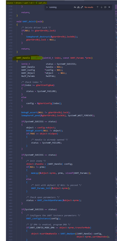
    Is the implementation of UART_close() and UART_open() APIs available on the public git repository?

    It will be very helpful if TI can share the implementation, especially the UART_open() API. Would like to see the implementation that actually sets the baud rate behind this API.

    And I did try to change the Clock Freq to 50000000 in SysConfig tool in the CCS and the M4F application just hang.

    Also, the code generated from SysConfig tool in "ti_power_clock_config.c" always uses the "TISCI_DEV_UART1_FCLK_CLK" as the clock source for UART1.

    SOC_ModuleClockFrequency gSocModulesClockFrequency[] = {
        { TISCI_DEV_UART1, TISCI_DEV_UART1_FCLK_CLK, 48000000 },
        { TISCI_DEV_MCU_UART0, TISCI_DEV_MCU_UART0_FCLK_CLK, 48000000 },
    
        { SOC_MODULES_END, SOC_MODULES_END, SOC_MODULES_END },
    };

    Is it possible to use other clock source as listed below in "tisci_clocks.h".

    #define TISCI_DEV_UART1_FCLK_CLK 0
    #define TISCI_DEV_UART1_FCLK_CLK_PARENT_USART_PROGRAMMABLE_CLOCK_DIVIDER_OUT1 1
    #define TISCI_DEV_UART1_FCLK_CLK_PARENT_HSDIV4_16FFT_MAIN_1_HSDIVOUT1_CLK 2
    #define TISCI_DEV_UART1_VBUSP_CLK 5

    My understanding that  "TISCI_DEV_UART1_FCLK_CLK"  is fixed to 48000000.

    Among the other 3 clock sources, which one is actually 160MHz or 192MHz? Is this clock source frequency is fixed or configurable?

    How to configure other clock source to produce 50000000? An actual working code implementation will be helpful.

    rgds,

    kc Wong

  • Greetings Kiung,

    If you have already installed the MCU PLUS SDK for AM62x, then you do not need to search anywhere else for the API.

    Both UART Open and Close implementation is available under source/drivers/uart/v0/uart_v0.c

    I hope this reference helps.

    Regards,

    Vaibhav

  • So, is it possible to use other clock source for UART1 in M4Fcore ? If yes, how ?

    #define TISCI_DEV_UART1_FCLK_CLK 0
    #define TISCI_DEV_UART1_FCLK_CLK_PARENT_USART_PROGRAMMABLE_CLOCK_DIVIDER_OUT1 1
    #define TISCI_DEV_UART1_FCLK_CLK_PARENT_HSDIV4_16FFT_MAIN_1_HSDIVOUT1_CLK 2
    #define TISCI_DEV_UART1_VBUSP_CLK 5

  • Hi Kiung,

    On a different family of processor, AM64x to be precise. We have the option for the user to select the UART frequency, but I am not seeing the same for AM62x. Moreover, once you select the new frequency in AM64x SysConfig, you actually get to see that the value reflects in the generated files from sysconfig. But in case of AM62x even if you change the value in sysconfig, it does not reflect in the generated files.

    AM64x SysConfig UART Frequency option dropdown available:


    There must be a reason behind it or might be a missed feature addition.

    Allow me few business days to check internally on this matter.

    But a quick fix would be you can go ahead and choose one of the frequencies mentioned in the AM62x TRM table.

    Let's say you want to go ahead with:

    Baud Rate: 19200

    Frequency: 192 MHz = 192000000

    Then copy the generated files from SysConfig, and paste it in the project directory itself. Now set SysConfig to be excluded from the build.

    Post this make sure you go ahead and make the following changes:

    1. In ti_drivers_config.c have you configuration as follows:

      static UART_Attrs gUartAttrs[CONFIG_UART_NUM_INSTANCES] =
      {
      {
      .baseAddr = CSL_MCU_UART0_BASE,
      .inputClkFreq = 192000000U,                              // changed here from 48 MHz to 192 MHz
      },
      };
    2. In ti_drivers_open_close.c have your configuration as follows:

      /* UART Driver Parameters */
      UART_Params gUartParams[CONFIG_UART_NUM_INSTANCES] =
      {
      {
      .baudRate = 19200,                                               // changed here from 115200 to 19200
      .dataLength = UART_LEN_8,
      .stopBits = UART_STOPBITS_1,
      .parityType = UART_PARITY_NONE,
      .readMode = UART_TRANSFER_MODE_BLOCKING,
      .readReturnMode = UART_READ_RETURN_MODE_FULL,
      .writeMode = UART_TRANSFER_MODE_BLOCKING,
      .readCallbackFxn = NULL,
      .writeCallbackFxn = NULL,
      .hwFlowControl = FALSE,
      .hwFlowControlThr = UART_RXTRIGLVL_16,
      .transferMode = UART_CONFIG_MODE_INTERRUPT,
      .skipIntrReg = FALSE,
      .uartDmaIndex = -1,
      .intrNum = 40U,
      .intrPriority = 4U,
      .operMode = UART_OPER_MODE_16X,
      .rxTrigLvl = UART_RXTRIGLVL_8,
      .txTrigLvl = UART_TXTRIGLVL_32,
      .rxEvtNum = 0U,
      .txEvtNum = 0U,
      },
      };

    Moreover in the file uart_v0.c, in the function UART_configInstance() your divisor value will be computed correctly based of the changed frequency and baud rate and the correctness can be verified with the table as shared above.

    Hope this helps.

    Let me know if you need more help.

    Regards,

    Vaibhav

  • Hi Vaibhav,

    Thanks for the infor.

    So, what is the value that we can set for the UART1 clock frequency?

    Is it just limited to 48 MHz, 92 MHz, 196 MHz and 160 MHz?

    Or it can be any value that we want?

    rgds,

    kc Wong

  • Hi Kiung,

    Thanks for your patience.

    I would suggest you to go ahead with the frequencies as mentioned in the table in the previous response.

    Regards,

    Vaibhav

  • The baud rate that we need is 3.125Mpbs. And that is requiring UART1 clock frequency to be 50MHz, but 50MHz does not seem to work, the M4F application just hang.

    UART 16x mode: Divisor value = Operating frequency / (16 x baud rate)
    1.0 = 50e6 / (16 * 3.125e6)


    I think the SysConfig tool has a defect, it only updates the "gSocModulesClockFrequency[]" in "ti_power_clock_config.c" file when setting different clock frequency.


    SOC_ModuleClockFrequency gSocModulesClockFrequency[] = {
        { TISCI_DEV_UART1, TISCI_DEV_UART1_FCLK_CLK, 50000000 },
        { TISCI_DEV_MCU_UART0, TISCI_DEV_MCU_UART0_FCLK_CLK, 48000000 },
    
        { SOC_MODULES_END, SOC_MODULES_END, SOC_MODULES_END },
    };

    It does not update the "gUartAttrs[]" in "ti_drivers_config.c" file, and it is fixed to 48MHz always. And by which requires a manual update by setting the "example.syscfg" to be excluded from the build.

    /* UART atrributes */
    static UART_Attrs gUartAttrs[CONFIG_UART_NUM_INSTANCES] =
    {
        {
            .baseAddr           = CSL_UART1_BASE,
            .inputClkFreq       = 48000000U,
        },
        {
            .baseAddr           = CSL_MCU_UART0_BASE,
            .inputClkFreq       = 48000000U,
        },
    };


  • Hi Kiung,

    I have shared this concern with the developer and raised an internal JIRA to track this issue.

    I will update you with further updates once I receive them.

    Regards,

    Vaibhav

  • Ok, thanks.

    If it only supports a set of limited value, then may be a drop-down list like AM64x SysConfig will be good.

    Else if it supports a range of value, then may be a little documentation of the valid clock frequency value will be helpful.

    That would be my suggestions.

  • Hi Kiung,

    Thanks for your response.

    I have considered your inputs on the dropdown option or a guide on valid clock frequency value.

    As said earlier, I will keep an eye on the JIRA and update you with activities on the same.

    Thanks for your patience.

    Regards,

    Vaibhav

  • Hi Kiung,

    Thank you very much for your patience.

    I wanted to provide you an update on the internal JIRA I raised for AM62x UART clock frequency not being effective and shown in the generated SysConfig files.

    The fix has been merged and will go into MCU PLUS SDK version 10.00.

    I am closing this thread now.

    Regards,

    Vaibhav

  • Hi Vaibhav,

    Thanks for your update.

    1. Also, I would like to suggest adding a new UART API to set baud rate.

    2. And shouldn't be the "Read and throw Erroneous bytes from RxFIFO" code block checks for "while (0 != errorVal)" instead of checking the errorVal with all the error bits set??? I think it is a defect.

    /mcu_plus_sdk_am62x_09_02_00_38/source/drivers/uart/v0/uart.h

    static inline uint8_t UART_getCharFifo(uint32_t baseAddr, uint8_t *readBuf)
    {
        uint8_t           readByte = 0;
        uint32_t          waitCount = UART_ERROR_COUNT;
        uint32_t          errorVal;
        uint32_t          lcrRegValue = 0;
    
        /* Preserving the current value of LCR. */
        lcrRegValue = HW_RD_REG32(baseAddr + UART_LCR);
    
        /* Switching to Register Operational Mode of operation. */
        HW_WR_REG32(baseAddr + UART_LCR, HW_RD_REG32(baseAddr + UART_LCR)
                                & 0x7FU);
    
        /* Read Rx Error Status */
        errorVal = HW_RD_REG32(baseAddr + UART_LSR) &
                 (UART_LSR_RX_FIFO_STS_MASK |
                  UART_LSR_RX_BI_MASK |
                  UART_LSR_RX_FE_MASK |
                  UART_LSR_RX_PE_MASK |
                  UART_LSR_RX_OE_MASK);
    
        /* Restoring the value of LCR. */
        HW_WR_REG32(baseAddr + UART_LCR, lcrRegValue);
    
        /* Read and throw Erroneous bytes from RxFIFO */
        while ((UART_LSR_RX_FIFO_STS_MASK |
                UART_LSR_RX_BI_MASK |
                UART_LSR_RX_FE_MASK |
                UART_LSR_RX_PE_MASK |
                UART_LSR_RX_OE_MASK) == errorVal)
        {
            readByte = (uint8_t) (HW_RD_REG32(baseAddr + UART_RHR) & 0xFFU);
            waitCount--;
            if (0U == waitCount)
            {
                break;
            }
    
            /* Preserving the current value of LCR. */
            lcrRegValue = HW_RD_REG32(baseAddr + UART_LCR);
    
            /* Switching to Register Operational Mode of operation. */
            HW_WR_REG32(baseAddr + UART_LCR, HW_RD_REG32(baseAddr + UART_LCR)
                                    & 0x7FU);
    
            /* Read Rx Error Status */
            errorVal = HW_RD_REG32(baseAddr + UART_LSR) &
                     (UART_LSR_RX_FIFO_STS_MASK |
                      UART_LSR_RX_BI_MASK |
                      UART_LSR_RX_FE_MASK |
                      UART_LSR_RX_PE_MASK |
                      UART_LSR_RX_OE_MASK);
    
            /* Restoring the value of LCR. */
            HW_WR_REG32(baseAddr + UART_LCR, lcrRegValue);
        }
    
        /* Read non-erroneous byte from RxFIFO */
        readByte = (uint8_t) (HW_RD_REG32(baseAddr + UART_RHR) & 0xFFU);
    
        return readByte;
    }

    rgds,

    kc Wong

  • Hi Kiung,

    Thank you for your response.

    1. Also, I would like to suggest adding a new UART API to set baud rate.

    2. And shouldn't be the "Read and throw Erroneous bytes from RxFIFO" code block checks for "while (0 != errorVal)" instead of checking the errorVal with all the error bits set??? I think it is a defect.

    I have taken your suggestions.

    Please expect responses in sometime.

    Regards,

    Vaibhav

  • Greetings Kiung,

    Thanks for your patience.

    I would like to suggest adding a new UART API to set baud rate.

    I would like to comment on this line. If we talk about making anew API for setting UART Baud Rate, then there will be similar requests like creating a API to set frequency/interrupt/polled and so on, so currently we have taken your suggestion into account and we will consider to include the API based on MR.

    Currently, I think the best approach would be to simply set it from SysConfig itself, given we are fixing the Frequency UART bug as well.

    And shouldn't be the "Read and throw Erroneous bytes from RxFIFO" code block checks for "while (0 != errorVal)" instead of checking the errorVal with all the error bits set??? I think it is a defect.

    I would need to talk about this to a concerned dev, please expect to hear from me once I have confirmed its a bug.

    Regards,

    Vaibhav