


Hi TI Team,
Currently, I am working on our custom board and trying to activate LVDS CH1 (odd) port. The sdk version is v9.02.
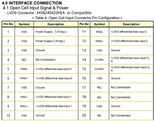
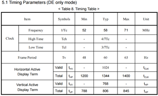
Previously, we had an RGB LCD screen that worked fine; now we need to use an LVDS single link 18bits LCD screen. The interface information is shown in the attached images. Referring to some articles on the forum, I have modified the DTS file and panel-simple.c as follows. However, the LVDS panel is not working properly and remains in bist mode.
DTS:
	panel {
		compatible = "boe,boe_ev150x0m";
		pinctrl-names = "default";
		pinctrl-0 = <&pinctrl_panel_en>;
		power-supply = <&vcc_5v0>;
		enable-gpios = <&main_gpio1 7 GPIO_ACTIVE_HIGH>;
		backlight = <&backlight>;

		/*
		* Note that the OLDI TX 0 transmits the odd set of pixels
		* while the OLDI TX 1 transmits the even set. This is a
		* fixed configuration in the IP integration and is not
		* changeable. The properties, "dual-lvds-odd-pixels" and
		* "dual-lvds-even-pixels" have been used to merely
		* identify if a Dual Link configuration is required.
		* But swapping them will cause an error in the dss driver.
		*/
		port@0 {
			//dual-lvds-odd-pixels;
			lcd_in0: endpoint {
				remote-endpoint = <&oldi_out0>;
			};
		};
	};

		main_oldi0_pins_default: main-oldi0-pins-default {
		pinctrl-single,pins = <
			AM62X_IOPAD(0x0260, PIN_OUTPUT, 0) /* (AA5) OLDI0_A0N */
			AM62X_IOPAD(0x025c, PIN_OUTPUT, 0) /* (Y6) OLDI0_A0P */
			AM62X_IOPAD(0x0268, PIN_OUTPUT, 0) /* (AD3) OLDI0_A1N */
			AM62X_IOPAD(0x0264, PIN_OUTPUT, 0) /* (AB4) OLDI0_A1P */
			AM62X_IOPAD(0x0270, PIN_OUTPUT, 0) /* (Y8) OLDI0_A2N */
			AM62X_IOPAD(0x026c, PIN_OUTPUT, 0) /* (AA8) OLDI0_A2P */
			AM62X_IOPAD(0x0278, PIN_OUTPUT, 0) /* (AB6) OLDI0_A3N */
			AM62X_IOPAD(0x0274, PIN_OUTPUT, 0) /* (AA7) OLDI0_A3P */
			AM62X_IOPAD(0x0280, PIN_OUTPUT, 0) /* (AC6) OLDI0_A4N */
			AM62X_IOPAD(0x027c, PIN_OUTPUT, 0) /* (AC5) OLDI0_A4P */
			AM62X_IOPAD(0x0288, PIN_OUTPUT, 0) /* (AE5) OLDI0_A5N */
			AM62X_IOPAD(0x0284, PIN_OUTPUT, 0) /* (AD6) OLDI0_A5P */
			AM62X_IOPAD(0x0290, PIN_OUTPUT, 0) /* (AE6) OLDI0_A6N */
			AM62X_IOPAD(0x028c, PIN_OUTPUT, 0) /* (AD7) OLDI0_A6P */
			AM62X_IOPAD(0x0298, PIN_OUTPUT, 0) /* (AD8) OLDI0_A7N */
			AM62X_IOPAD(0x0294, PIN_OUTPUT, 0) /* (AE7) OLDI0_A7P */
			AM62X_IOPAD(0x02a0, PIN_OUTPUT, 0) /* (AD4) OLDI0_CLK0N */
			AM62X_IOPAD(0x029c, PIN_OUTPUT, 0) /* (AE3) OLDI0_CLK0P */
			AM62X_IOPAD(0x02a8, PIN_OUTPUT, 0) /* (AE4) OLDI0_CLK1N */
			AM62X_IOPAD(0x02a4, PIN_OUTPUT, 0) /* (AD5) OLDI0_CLK1P */
		>;
	};

	&dss {
	status = "okay";
	pinctrl-names = "default";
	pinctrl-0 = <&main_oldi0_pins_default &main_dss0_pins_default>;
};

&dss_ports {
	#address-cells = <1>;
	#size-cells = <0>;

		/* VP1: LVDS Output (OLDI TX 0) */
	port@0 {
		reg = <0>;
		oldi_out0: endpoint {
			remote-endpoint = <&lcd_in0>;
		};
	};
};
panel-simple.c:
static const struct drm_display_mode boe_ev150x0m_mode = {
	.clock = 58000,
	.hdisplay = 1024,
	.hsync_start = 1024 + 80,
	.hsync_end = 1024 + 80+ 80,
	.htotal = 1024 + 80 + 80 + 40,
	.vdisplay = 768,
	.vsync_start = 768 + 10,
	.vsync_end = 768 + 10 + 10,
	.vtotal = 768 + 10 + 10 + 10,
};

static const struct panel_desc boe_ev150x0m = {
	.modes = &boe_ev150x0m_mode,
	.bpc = 6,
	.num_modes = 1,
	.size = {
		.width = 304,
		.height = 228,
	},
	.delay = {
		.prepare = 50,
		.disable = 50,
	},
	.bus_format = MEDIA_BUS_FMT_RGB666_1X7X3_SPWG,
	.bus_flags = DRM_BUS_FLAG_DE_HIGH,
	.connector_type = DRM_MODE_CONNECTOR_LVDS,
};
lcd information:
Below are kmsprint and kmstest results, and register 0x3020A160 and 0x108700.
root@am62xx-evm:~# kmsprint
Connector 0 (40) LVDS-1 (connected)
  Encoder 0 (39) LVDS
    Crtc 0 (38) 1024x768@59.38 58.000 1024/80/80/40/? 768/10/10/10/? 59 (59.38) 0x0 0x48
      Plane 0 (31) fb-id: 48 (crtcs: 0) 0,0 1024x768 -> 0,0 1024x768 (AR12 AB12 RA12 RG16 BG16 AR15 AB15 AR24 AB24 RA24 BA24 RG24 BG24 AR30 AB30 XR12 XB12 RX12 XR15 XB15 XR24 XB24 RX24 BX24 XR30 XB30 YUYV UYVY NV12)
        FB 48 1024x768
root@am62xx-evm:~# kmstest
Connector 0/@40: LVDS-1
  Crtc 0/@38: 1024x768@59.38 58.000 1024/80/80/40/? 768/10/10/10/? 59 (59.38) 0x0 0x48
  Plane 0/@31: 0,0-1024x768
    Fb 49 1024x768-XR24
press enter to exit

root@am62xx-evm:~# devmem2 0x00108700
/dev/mem opened.
Memory mapped at address 0xffff971f2000.
Read at address  0x00108700 (0xffff971f2700): 0x80000002
root@am62xx-evm:~# devmem2 0x3020A160
/dev/mem opened.
Memory mapped at address 0xffffa5125000.
Read at address 0x3020A160 (0xffffa5125160): 0x00001185
I checked the clock signal using an oscilloscope and found that the actual clock frequency was only half of what I configured. Specifically, the configured frequency was 58MHz, but the actual measured frequency was around 29MHz. How can I resolve this issue and get the panel work.
Best regards.
