This thread has been locked.

If you have a related question, please click the "Ask a related question" button in the top right corner. The newly created question will be automatically linked to this question.

AM6442: Code samples or pointers for actually using PPS inside the PRU?

Part Number: AM6442


Hello there!

Beyond the FAQ for "How to synchronize the PRU IEP timer with Linux system time?", is there a good example for getting a timestamp updated in the PRU?

Our use case:

We have been successfully using a PRU for sampling data. Now we need to get serious about tagging samples with the PTP clock.

We want to use the first PTP clock to send a PPS and use it in a PRU.

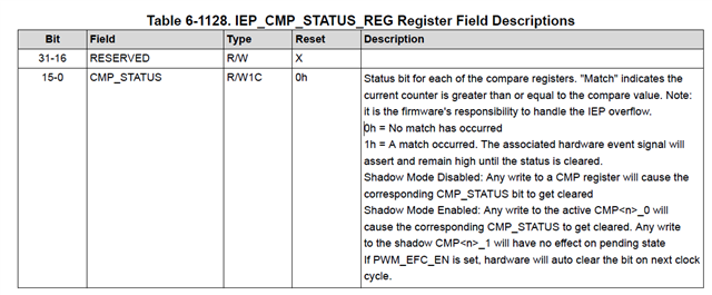
Once we get the PPS we need to use the timer to compensate a PRU clock for drift, that we intend to use to sample events that happen inside of the PRU. We've seen that there are industrial registers that can do gradual compensation. Should we be using those?

With the FAQ and posts that are around we can get to having the PPS in the PRU and in a GPIO, but after that we'll have to use the industrial components.

Documentation is a bit sparse and I'm looking for code samples or pointers.  I've seen related code that use the industrial registers as part of Ethernet examples, hard to see details there.

If I'm not looking at the right sources or the right lines in the sources I would appreciate if you point me in the right direction.

Best regards.

  • Hello Nelson,

    At this point in time, we have not developed a more in-depth example - unfortunately examples demonstrating internal time-sync between processor cores have been the ones to get pushed back the last couple releases to make sure other features have enough development time. I can't give an exact timeframe for when those examples will get prioritized, other than we will NOT be adding any new ones for SDK 10.0.

    Are you using the IEP timer, or a different timer?

    Regards,

    Nick

  • > Are you using the IEP timer, or a different timer?

    We'd like to use the IEP timer. What example can you recommend?

    At this point counting instructions. We started debugging taking data out of the PRUs first and the handshaking with the Linux process. We're using one PRU for sampling and another one for IPC with Linux.

    So timing is our priority now. First having better timings. Then making PTP work to sync a number of devices in a local network.

    Regards.

  • Hello Nelson,

    There is a simple IEP timer example in the PRU Software Support Package - it does not really give much guidance on how to use any of the IEP's fancy features though: https://git.ti.com/cgit/pru-software-support-package/pru-software-support-package/tree/examples/am335x/PRU_IEP

    I expect the IEP timer in AM64x to be similar or identical, but the register names might have changed. If you want to take advantage of the header file similar to that example, the AM64x one is here: https://git.ti.com/cgit/pru-software-support-package/pru-software-support-package/tree/include/am64x/pru_iep.h

    I am going to reassign your thread to another team member to see if they are aware of any good PRU examples where the IEP timer is used.

    Regards,

    Nick

  • Hello Nelson,

      IEP timer can be used to synchronize to external time reference. The basics are to measure delta time between local time and external time, and tune IEP timer using compensation hardware. Compensation hardware can be immediate or span out over a period. E.g. if you want to tune IEP timer by 7 ns over 1 second period you set:

    IEP_GLOBAL_CFG_REG.COMP_INC = DEFAULT_INC +1/-1 (1 ns faster or slower than default_inc)

    IEP_SLOW_COMPEN_REG.SLOW_COMPEN_CNT = 1 second / 7  -> 142857143 ns

    ICSS peripheral registers above can be programmed from PRU or ARM.

    It is not clear to me how you do your delta T measurement. Is the external time reference an internal event or external signal? In any case you can time-stamp internal or external events using IEP capture register and LATCH input for external. You can also use IEP SYNC output to generate a 1 PPS signals.

    BR,

       Thomas

  • Hi Thomas, thanks for the reply.

    If the compensation is automatic that sounds great. What I'd like to do is route a signal from the PTP0 clock to the PRU and then compensate an IEP timer. I've been reading and the timer makes more sense now than before, but I still need to get there.

    Yesterday I resumed the task and started following Nick's tips and this post in this forum to get the timer working first, which is a prerequisite for the task. I'm using PRU1_0 (am64x-pru1_0-fw).

    I can check the value of the timer and it's wrapping! So that's progress. I could use this but getting an interrupt sounds better as it would allow having the PRU sleep a bit while waiting for the interrupt.

    While trying to receive the interrupt I can get either to the path marked with the comment "// Path A"  or to "// Path B", but I haven't been able to get the interrupt.

    In my intc_map_0.h I only have this definition: {17, 0, 0} , I think I need another entry. What am I missing here?

    // TODO: No longer need to do this? How to do in am64x?
    //CT_CFG.SYSCFG_bit.STANDBY_INIT = 0;
    CT_IEP0.global_cfg_reg_bit.cnt_enable = 0;

    CT_IEP0.cmp_cfg_reg_bit.shadow_en = 0;
    CT_IEP0.cmp_cfg_reg_bit.shadow_en = 1;

    CT_IEP0.count_reg0_bit.count_lo = 0xFFFFFFFF;
    CT_IEP0.count_reg1_bit.count_hi = 0xFFFFFFFF;
    CT_IEP0.global_status_reg_bit.cnt_ovf = 1;
    CT_IEP0.cmp_status_reg_bit.cmp_status = 0xFFFF;
    CT_IEP0.cmp0_reg1_bit.cmp0_1 = 250000 * 2; // 2 seconds @ 250Mhz

    CT_IEP0.cmp_cfg_reg_bit.cmp_en = (1u << 8) | (1u << 0);
    CT_IEP0.cmp_cfg_reg_bit.cmp0_rst_cnt_en = 1;

    CT_IEP0.global_cfg_reg_bit.default_inc = 1;

    CT_IEP0.compen_reg_bit.compen_cnt = 0;

    CT_INTC.STATUS_CLR_INDEX_REG_bit.STATUS_CLR_INDEX =(unsigned int)(1<<31) ;

    // Test 1:
    // If I terminate the program I can read that the timer wraps! Great.
    // __delay_cycles(510000);
    // __panic(CT_IEP0.count_reg0);
    while ((__R31 & (unsigned int)(1<<31)) == 0) {
    // Path A
    }
    // Path B
  • Hi Nelson,

       the examples from AM335x work with INTC and polling. On AM64x we have more capabilities using task manager triggered from IEP compare events.

    Here a system level block diagram which shows the various event generation and PRU interrupts.

    Here a view lines which configure task manager for ICSS_G0 PRU0 when IEP CMP0 hits. On IEP wrap around with cmp0 hit PRU0 jumps to task tm_ch4_send() within 2 PRU cycles. 

    void tm_ch4_send();
    
    int main(void)
    {
    
    ....
    
    /* ---------- task manager configuration ------------------- */
            // disable task manager
            asm("   tsen 0");
    
            // clear event from previous debug.
            HW_WR_REG32(0x3002a000, 0x0fff);
            asm("   xin     252, &r0.b3,1");
            asm("   nop ");
            asm("   nop ");
    
            HW_WR_REG32(0x3002a000, 0x0000);
    
            // configure task manager for iep_task, TS2 is highest priority and can pre-empt TS1
            //  general purpose mode = 2 ,
            //  TS2_S0 = tm_ch4_send (bit 7)
            HW_WR_REG32(0x3002a000, 0x0182);
    
            // set address of tm_ch4_send
            // TS2_0
            HW_WR_REG32(0x3002a01c, (unsigned int) tm_ch4_send);
    
            // set TS2 trigger to
            // S2_0 (bit 7-0)  iep0_cmp0 = 16
            // S2_1 (bit 15-8) iep0_cmp1 = 17
            HW_WR_REG32(0x3002a040, 0x1110);
    

    I typically put the task in assembly file as it uses broadside functions (XIN/XOUT) for context save:

       .global     tm_ch4_send

    ; ----------------------------------------------------------------------------
    ; task tm_ch4_send
    ;
    ; ----------------------------------------------------------------------------

    tm_ch4_send:
        xout    BANK0_ID, &r0, 27*4     ; save R0-r26

       .. your code goes here

        xin     TM_YIELD_XID, &R0.b3,1  ; exit task after two instructions/cycles
        nop
        xin    BANK0_ID, &r0, 27*4     ; save R0-r26

    Advantage of using task manager is that you configure multiple tasks using any of the IEP compare hit events whereas INTC has only a single IEP hit event as input.

    - Thomas

  • Thanks a lot Thomas.

    I used the instructions and pointers from the SDKs and tried to adapt for PRU1_0. It seems that "TSEN 1" was needed.
    Testing with shared memory.

    What I get now is that the ASM handler is called, but only once.
    Better than before!

    Sharing the code. What am I doing wrong?

    void __panic(uint32_t error_code) {
     uint32_t *icssg_shared_mem_ = (uint32_t *)SHARED_ICSSG_MEM;
     *icssg_shared_mem_ = 0xdeadbeef;
     *(icssg_shared_mem_ + 1) = error_code;
    }
    
    extern void tm_ch4_send();
    
    inline void config_task_manager() {
     // disable task manager, .word 0x32800000 to enable
     // pru_io/firmware/common/icss_tm_macros.in
     __asm(" .word 0x32000000;"); // TSEN 0
    
     // clear event from previous debug.
     HW_WR_REG32(PRU1_0_TASK_MGR_REG_BASE, 0x0fff);
     asm(" xin 252, &r0.b3,1");
     asm(" nop ");
     asm(" nop ");
    
     HW_WR_REG32(PRU1_0_TASK_MGR_REG_BASE, 0x0000);
    
     // configure task manager for iep_task, TS2 is highest priority and can
     // pre-empt TS1
     // general purpose mode = 2 ,
     // TS2_S0 = tm_ch4_send (bit 7)
     HW_WR_REG32(PRU1_0_TASK_MGR_REG_BASE, 0x0182);
     // // set address of tm_ch4_send
     // // TS2_0
     HW_WR_REG32(PRU1_0_TASK_MGR_REG_BASE + 0x1c, (unsigned int)tm_ch4_send);
    
     // set TS2 trigger to
     // S2_0 (bit 7-0) iep0_cmp0 = 16
     // S2_1 (bit 15-8) iep0_cmp1 = 17
     HW_WR_REG32(PRU1_0_TASK_MGR_REG_BASE + 0x40, 0x1110);
     __asm(" .word 0x32800000;"); // TSEN 1
    }
    
    void test_iep() {
     /* Disable counter */
     CT_IEP0.global_cfg_reg_bit.cnt_enable = 0;
     /* Switch to 32-bit mode */
     CT_IEP0.cmp_cfg_reg_bit.shadow_en = 0;
     CT_IEP0.cmp_cfg_reg_bit.shadow_en = 1;
    
     /* Reset Count register */
     CT_IEP0.count_reg0_bit.count_lo = 0xFFFFFFFF;
     CT_IEP0.count_reg1_bit.count_hi = 0xFFFFFFFF;
    
     /* Clear overflow status register */
     CT_IEP0.global_status_reg_bit.cnt_ovf = 1;
    
     /* Clear compare status */
     CT_IEP0.cmp_status_reg_bit.cmp_status = 0xFFFF;
    
     /* Set compare value */
     CT_IEP0.cmp0_reg1_bit.cmp0_1 = 250000;
    
     /* Enable CMP0 and reset on event */
     CT_IEP0.cmp_cfg_reg_bit.cmp_en = (1u << 8) | (1u << 0);
     CT_IEP0.cmp_cfg_reg_bit.cmp0_rst_cnt_en = 1;
    
     /* Set increment value */
     CT_IEP0.global_cfg_reg_bit.default_inc = 1;
    
     /* Disable compensation */
     CT_IEP0.compen_reg_bit.compen_cnt = 0;
    
    // Not needed, I think.
     CT_INTC.STATUS_CLR_INDEX_REG_bit.STATUS_CLR_INDEX = (unsigned int)(1 << 31);
    
     /* Enable counter */
     CT_IEP0.global_cfg_reg_bit.cnt_enable = 1;
    
     config_task_manager();
    
     uint32_t i = 0;
     
    
     while (1) {
     {
     volatile uint32_t *icssg_shared_mem_ = (uint32_t *)SHARED_ICSSG_MEM;
     // tm_ch4_send sets this value. Does it only once.
     while (*icssg_shared_mem_ != 0xff);
     *icssg_shared_mem_ = 0;
     // We get here once!
     *(icssg_shared_mem_ + 1) = ++i;
     }
     __delay_cycles(100);
    
     {
     volatile uint32_t *icssg_shared_mem_ = (uint32_t *)SHARED_ICSSG_MEM;
     while (*icssg_shared_mem_ != 0xff);
     // We never get here, so the handler is only called once.
     __panic(7);
     }
     } // while(1)
    }
    ------------
    global     tm_ch4_send
    
    ; ----------------------------------------------------------------------------
    ; task tm_ch4_send
    ;
    ; ----------------------------------------------------------------------------
    
    TM_YIELD_XID        .set 252
    BANK0_ID             .set   10
    
    tm_ch4_send:
        xout    BANK0_ID, &r0, 27*4     ; save R0-r26
            LDI32     r1, 0x00010000        ;
            LDI32     r2, 0x000000ff        ;
            SBBO      &r2, r1, 0, 4         ;
        nop
        xin     TM_YIELD_XID, &R0.b3,1  ; exit task after two instructions/cycles
        nop
        xin    BANK0_ID, &r0, 27*4     ; save R0-r26


    PS: There should be a __halt() at the end of the  __panic function, I deleted code that I have there but I should have kept this line.

  • Hi Nelson,

      to get next compare hit event to trigger task you need to clear the compare status register.

    Two options here:

    1. Set auto clear in configuration register

            HW_WR_REG16(0x30026042, 1);  /* ICSSG_SA_MX_REG: set PWM_EFC_EN mode, auto clear cmp pending flags */

    2. Manual clear of IEP_CMP_STATUS_REG in task

    I hope that solves the problem of one time task.

    In your task you write 4 bytes to ICSS shared RAM (offset 0x0001 0000).

    You can use here sbco r2,c28,0,4 after initializing c28:

       // configure C28 to point to ICSS_shared
        HW_WR_REG32(0x30022028, 0x0100);

    You still need to adapt to PRU1 here.

    I hope this helps.

    - Thomas

  • Thanks a lot, things worked.

    #define PRU1_0_TASK_MGR_REG_BASE (0x300aa000UL)
    #define SHARED_ICSSG_MEM (0x10000)
    
    static inline void HW_WR_REG32(uint32_t addr, uint32_t value) {
      *(volatile uint32_t *)((uintptr_t)addr) = value;
      return;
    }
    
    // callback.asm, sets shared memory location to 0.
    void tm_ch4_send();
    
    inline void config_task_manager() {
      // disable task manager, pru_io/firmware/common/icss_tm_macros.in
      __asm(" .word 0x32000000;");  // TSEN 0
    
      // clear event from previous debug.
      HW_WR_REG32(PRU1_0_TASK_MGR_REG_BASE, 0x0fff);
      asm("   xin     252, &r0.b3,1");
      asm("   nop ");
      asm("   nop ");
    
      HW_WR_REG32(PRU1_0_TASK_MGR_REG_BASE, 0x0000);
    
      // configure task manager for iep_task, TS2 is highest priority and can
      // pre-empt TS1
      //  general purpose mode = 2,
      //  TS2_S0 = tm_ch4_send (bit 7)
      HW_WR_REG32(PRU1_0_TASK_MGR_REG_BASE, 0x0182);
      // // set address of tm_ch4_send
      // // TS2_0
      HW_WR_REG32(PRU1_0_TASK_MGR_REG_BASE + 0x1c, (unsigned int)tm_ch4_send);
      // set TS2 trigger to
      // S2_0 (bit 7-0)  iep0_cmp0 = 16
      // S2_1 (bit 15-8) iep0_cmp1 = 17
      HW_WR_REG32(PRU1_0_TASK_MGR_REG_BASE + 0x40, 0x1110);
      // enable task manager
      __asm(" .word 0x32800000;");  // TSEN 1
    }
    
    void configure_counter(uint32_t cmp_value) {
      /* Disable counter */
      CT_IEP0.global_cfg_reg_bit.cnt_enable = 0;
      /* Important, enables next event when CMP_STATUS is set */
      CT_IEP0.cmp_cfg_reg_bit.shadow_en = 1;
    
      /* Reset Count register */
      CT_IEP0.count_reg0_bit.count_lo = 0xFFFFFFFF;
      CT_IEP0.count_reg1_bit.count_hi = 0xFFFFFFFF;
    
      /* Clear overflow status register */
      CT_IEP0.global_status_reg_bit.cnt_ovf = 1;
    
      /* Clear compare status */
      CT_IEP0.cmp_status_reg_bit.cmp_status = 0xFFFF;
    
      /* Set compare value */
      CT_IEP0.cmp0_reg1_bit.cmp0_1 = cmp_value;
    
      /* Enable CMP0 and reset on event */
      CT_IEP0.cmp_cfg_reg_bit.cmp_en = (1u << 8) | (1u << 0);
      CT_IEP0.cmp_cfg_reg_bit.cmp0_rst_cnt_en = 1;
    
      /* Set increment value */
      CT_IEP0.global_cfg_reg_bit.default_inc = 1;
    
      /* Disable compensation */
      CT_IEP0.compen_reg_bit.compen_cnt = 0;
    
      /* Enable counter */
      CT_IEP0.global_cfg_reg_bit.cnt_enable = 1;
    }
    
    const int32_t kTimerCount = 250000000; // 1s @ 250MHz.
    
    void test_iep() {
      config_task_manager();
      configure_counter(kTimerCount);
      uint32_t i = 0;
      volatile uint32_t *icssg_shared_mem_ = (uint32_t *)SHARED_ICSSG_MEM;
      while (1) {
        *icssg_shared_mem_ = 1;
        while (*icssg_shared_mem_);
        CT_IEP0.cmp_status_reg_bit.cmp_status = 1;
        *(icssg_shared_mem_ + 1) = ++i;  // sudo devmem2 0x30090004
      }
    }
    

    I used the manual clear with shadow mode enabled. I was surprised that what worked was setting this register to 1.

         CT_IEP0.cmp_status_reg_bit.cmp_status = 1;

    We have been researching PTP and PPSs. That is what we'll try next, DTS is already in place.

    Also, a wave generated while counting for 1us with the IEP.


    Scope with wave generated with IEP timer

  • Hello again.

    We could not make the PPS signal work, or were unable to check it was working.

    We added the following to pinctrl-single,pins in the DTS.

        TS_OFFSET(15,22)
        TS_OFFSET(14,22)
        TS_OFFSET(13,22)
        TS_OFFSET(12,22)

    Also enabled PRG1_PRU0_GPO19 as input with this command:

        devmem2 0xf4110 w 0x0

    Once PPS has been enabled, say with:

        echo 1 > /sys/class/ptp/ptp0/pps_enable

    With the command "ppstest /dev/pps0" I can see the PPS is working.

    What should I expect to see in the IEP register to know things are working?

        I am trying to check CT_IEP1.digio_data_in_raw_reg .

    Also wondering what the configuration for the IEP register should be.

    Regards.

     
  • Hi Nelson,

       PRG1_PRU0_GPO19 PADCONFIG65 is at 0x000F4104

       PRG1_PRU1_GPO2 PADCONFIG68  is at 0x000F4110

    for manual pad configuration you first need to unlock register access.

    Here an example on how to set pad config from PRU:

    /* ---------- pin-mux configuration --------------------- */
    
            // unlock PADMMR config register
            // partition 0
            HW_WR_REG32(0x000f1008, 0x68EF3490);
            HW_WR_REG32(0x000f100c, 0xD172BC5A);
    
            // unlock PADMMR config register
            // partition 1
            HW_WR_REG32(0x000f5008, 0x68EF3490);
            HW_WR_REG32(0x000f500c, 0xD172BC5A);
    
            // PERIFIF0_RX - also PRU0_GPI13 if selected - BP.15
            HW_WR_REG32(0x000F4194, 0x00040001);
            // PERIFIF1_RX - also PRU0_GPI14 if selected - BP.14
            HW_WR_REG32(0x000F4198, 0x00040001);
    
    
            // PERIFIF0_tx PRU0_GPO1 output - BP.32
            HW_WR_REG32(0x000F4164, 0x00010000);
            // PERIFIF0_tx_en PRU0_GPO2 output - BP-31
            HW_WR_REG32(0x000F4168, 0x00010000);
    

    I am missing the context with PPS, PTS, DTS and how it relates to IEP. I would need more background info on what you try to accomplish to make proper suggestions.

    PTS and DTS are time stamps which you want to capture from external signal or internal events. External signal capture could be done with IEP LATCH inputs  for example. IEP Latch goes through time sync router and need to be routed first if you want to connect to external signal.

    - Thomas

  • Thanks Thomas.

    What we want to achieve is:

    ptp0 -> PPS signal -> timesync router -> latch input -> IEP register.

    We thought we had configured the timesync router by adding the following entries to "pinctrl-single,pins" in the DTS.

      TS_OFFSET(15,22)
      TS_OFFSET(14,22)
      TS_OFFSET(13,22)
      TS_OFFSET(12,22)

    So, after the help in this thread we can actually use an IEP register. Now we need to capture this signal to have an external reference and finally timestamp events. Almost there.

  • Hi Nelson,

    here the time sync router config to use external LATCH_IN signals

    ; time sync router PRG1_IEP0_EDC_LATCH_IN0

        ldi32   r2, 0x00a40024     ; outEvent IEP0 LATCH_IN0

        ldi32   r3, 0x00010008     ; inEvent IEP0 LATCH_IN0

        sbbo    &r3, r2, 0, 4


    ; time sync router PRG1_IEP0_EDC_LATCH_IN1

        ldi32   r2, 0x00a40028     ; outEvent IEP0 LATCH_IN1

        ldi32   r3, 0x00010009     ; inEvent IEP0 LATCH_IN1

        sbbo    &r3, r2, 0, 4

    LATCH_IN maps to CAP6R which can be used as an event to trigger task manager similar to this:

    Capture event is cleared when you read the capture register.

    - Thomas

  • // clang-format off
    #include "./Dependencies/intc_map_0.h"
    #include "./Dependencies/resource_table.h"
    #include <stdint.h>
    #include <pru_ctrl.h>
    #include <pru_intc.h>
    
    #include "./pru_registers.h" // __R30 and __R31, avoid IDE warnings.
    
    // clang-format on
    
    #define PRU1_0_TASK_MGR_REG_BASE (0x300aa000UL)
    #define SHARED_ICSSG_MEM (0x10000)
    
    void __panic(uint32_t error_code) {
      uint32_t *icssg_shared_mem_ = (uint32_t *)SHARED_ICSSG_MEM;
      *icssg_shared_mem_ = 0xdeadbeef;
      *(icssg_shared_mem_ + 1) = error_code;
      __halt();
    }
    
    
    // callback.asm, sets shared memory location to 0.
    void tm_ch4_send();
    
    #define PRU1_0_TASK_MGR_REG_BASE (0x300aa000UL)
    #define SHARED_ICSSG_MEM (0x10000)
    
    static inline void HW_WR_REG32(uint32_t addr, uint32_t value) {
      *(volatile uint32_t *)((uintptr_t)addr) = value;
      return;
    }
    
    #define AM64X_IOPAD(pa, val, muxmode)           (((pa) & 0x1fff)) ((val) | (muxmode))
    
    void pad_config() {
      /* ---------- pin-mux configuration --------------------- */
    
            // unlock PADMMR config register
            // partition 0
            HW_WR_REG32(0x000f1008, 0x68EF3490);
            HW_WR_REG32(0x000f100c, 0xD172BC5A);
    
            // unlock PADMMR config register
            // partition 1
            HW_WR_REG32(0x000f5008, 0x68EF3490);
            HW_WR_REG32(0x000f500c, 0xD172BC5A);
    
            // PERIFIF0_RX - also PRU0_GPI13 if selected - BP.15
            HW_WR_REG32(0x000F4194, 0x00040001);
            // PERIFIF1_RX - also PRU0_GPI14 if selected - BP.14
            HW_WR_REG32(0x000F4198, 0x00040001);
    
    
            // PERIFIF0_tx PRU0_GPO1 output - BP.32
            HW_WR_REG32(0x000F4164, 0x00010000);
            // PERIFIF0_tx_en PRU0_GPO2 output - BP-31
            HW_WR_REG32(0x000F4168, 0x00010000);
    }
    
    // callback.asm, sets shared memory location to 0.
    void tm_ch4_send();
    
    inline void config_task_manager() {
      // disable task manager, pru_io/firmware/common/icss_tm_macros.in
      __asm(" .word 0x32000000;");  // TSEN 0
    
      // clear event from previous debug.
      HW_WR_REG32(PRU1_0_TASK_MGR_REG_BASE, 0x0fff);
      asm("   xin     252, &r0.b3,1");
      asm("   nop ");
      asm("   nop ");
    
      HW_WR_REG32(PRU1_0_TASK_MGR_REG_BASE, 0x0000);
    
      // configure task manager for iep_task, TS2 is highest priority and can
      // pre-empt TS1
      //  general purpose mode = 2,
      //  TS2_S0 = tm_ch4_send (bit 7)
      HW_WR_REG32(PRU1_0_TASK_MGR_REG_BASE, 0x0182);
      // // set address of tm_ch4_send
      // // TS2_0
      HW_WR_REG32(PRU1_0_TASK_MGR_REG_BASE + 0x1c, (unsigned int)tm_ch4_send);
      // set TS2 trigger to
      // S2_0 (bit 7-0)  iep0_cmp0 = 16
      // S2_1 (bit 15-8) iep0_cmp1 = 17
      HW_WR_REG32(PRU1_0_TASK_MGR_REG_BASE + 0x40, 0x1110);
      // enable task manager
      __asm(" .word 0x32800000;");  // TSEN 1
    }
    
    void configure_counter(uint32_t cmp_value) {
      /* Disable counter */
      CT_IEP0.global_cfg_reg_bit.cnt_enable = 0;
      /* Important, enables next event when CMP_STATUS is set */
      CT_IEP0.cmp_cfg_reg_bit.shadow_en = 1;
    
      /* Reset Count register */
      CT_IEP0.count_reg0_bit.count_lo = 0xFFFFFFFF;
      CT_IEP0.count_reg1_bit.count_hi = 0xFFFFFFFF;
    
      /* Clear overflow status register */
      CT_IEP0.global_status_reg_bit.cnt_ovf = 1;
    
      /* Clear compare status */
      CT_IEP0.cmp_status_reg_bit.cmp_status = 0xFFFF;
    
      /* Set compare value */
      CT_IEP0.cmp0_reg1_bit.cmp0_1 = cmp_value;
    
      /* Enable CMP0 and reset on event */
      CT_IEP0.cmp_cfg_reg_bit.cmp_en = (1u << 8) | (1u << 0);
      CT_IEP0.cmp_cfg_reg_bit.cmp0_rst_cnt_en = 1;
    
      /* Set increment value */
      CT_IEP0.global_cfg_reg_bit.default_inc = 1;
    
      /* Disable compensation */
      CT_IEP0.compen_reg_bit.compen_cnt = 0;
    
      /* Enable counter */
      CT_IEP0.global_cfg_reg_bit.cnt_enable = 1;
    }
    
    const int32_t kTimerCount = 250000000; // 1s @ 250MHz.
    
    uint32_t config_external_latch(); // in asm
    
    void main() {
    
      pad_config();
    
      HW_WR_REG32(0x00a40024 , 0x00010008);
      HW_WR_REG32(0x00a40028, 0x00010009);
      
      config_task_manager();
      configure_counter(kTimerCount);
    
      uint32_t i = 0;
      volatile uint32_t *icssg_shared_mem_ = (uint32_t *)SHARED_ICSSG_MEM;
      while (1) {
        *icssg_shared_mem_ = 1;
        while (*icssg_shared_mem_);
        CT_IEP0.cmp_status_reg_bit.cmp_status = 1;
        *(icssg_shared_mem_ + 1) = ++i;  // sudo devmem2 0x30090004
        *(icssg_shared_mem_ + 2) = CT_IEP0.capr6_reg0;
        *(icssg_shared_mem_ + 3) = *((volatile int32_t*)0x300AE054); 
      }
    }
    Hi Thomas.

    We've integrated your pointers (except the ISR for CAP6R that we didn't manage to set up).

    Do you think I should be seeing a value in this register?

    CT_IEP0.capr6_reg0

    I think we got to the point where we're doing trial and error that is no longer productive. Hints appreciated!

     echo 1 > /sys/class/ptp/ptp0/pps_enable && ppstest /dev/pps0 
    trying PPS source "/dev/pps0"
    found PPS source "/dev/pps0"
    ok, found 1 source(s), now start fetching data...
    source 0 - assert 52.000000011, sequence: 1 - clear  0.000000000, sequence: 0
    source 0 - assert 53.000000011, sequence: 2 - clear  0.000000000, sequence: 0
    source 0 - assert 54.000000011, sequence: 3 - clear  0.000000000, sequence: 0
    source 0 - assert 55.000000011, sequence: 4 - clear  0.000000000, sequence: 0
    

  • Hi Nelson,

      the example I provided for pad config does not match your use case. You need to adapt pin-mux address to the LATCH IN signal.

    ; pin-mux configuration - PRG1_IEP0_EDC_LATCH_IN0, -> PRU0
        ldi32    r2, 0x000F4100  // ICSS_G1 LATCH
        ldi32    r3, 0x00040002
        sbbo     &r3, r2, 0, 4

    r2 has address of PIN you want to configure. See https://www.ti.com/lit/ds/symlink/am6411.pdf table 5.1 for correct address. 0xF4100 sets pinmux for LATCH_IN0 input on ICSS_G1.   For ICSS_G0 the address is 0x000F41A8.

    Time sync router config to map LATCH_IN0 pin (ICSS_G1 IEP0) to LATCH_IN capture unit on IEP0 of ICSS_G1 is correct.

    In order to see capture value in CAP6R you need to enable capture:

    ; enable capture mode for latch 1 and 0

      ldi32  r2, 0x0003FFC0

      sbco    &r2.b0, c26, ICSS_IEP_CAP_CFG_REG, 4

    See Table 6-1082. IEP_CAP_CFG_REG Register Field Descriptions in TRM.

    r2 values of 0x0003FFC0 enables external capture on LATCH_IN0 and LATCH_IN1.

    After setting correct:

    - PRG1_IEP0_EDC_LATCH_IN0 pin configuration

    - TIME sync router configuration

    - IEP CAP6R configuratoin

    you should see time stamps in CAP6R register. When you read that register It will clear the capture status.

    After you get the capture values you can enable task manager with trigger 38 = IEP_CAPR[0].

    BR,

      Thomas 

  • Thanks a lot Thomas for your guidance!

    What do you think can be the average nanosecond latency until the ISR for the event is called?

    This is the Hello World that ended up working for us. Using ICSSG1, PRU1.

    echo 1 > /sys/class/ptp/ptp0/pps_enable # Blink starts
    echo 0 > /sys/class/ptp/ptp0/pps_enable # Blink stops


    We have a led connected to mcu_gpio0_6 .

    #include <stdint.h>
    #include "./Dependencies/intc_map_0.h"
    #include "./Dependencies/resource_table.h"
    #include "./pru_registers.h" // __R30 and __R31, avoid IDE warnings.
    
    #define PRU1_0_TASK_MGR_REG_BASE (0x300aa000UL)
    #define SHARED_ICSSG_MEM (0x10000)
    
    inline void HW_WR_REG32(uint32_t addr, uint32_t value) {
      *(volatile uint32_t *)((uintptr_t)addr) = value;
    }
    
    // mcu_gpio0_6, red led.
    inline void config_leg() {
      HW_WR_REG32(0x04084018, 0x00000007);
      HW_WR_REG32(0x04201010, 0xFFFFFFBF);
    }
    
    inline void set_led() { HW_WR_REG32(0x04201018, 0x00000040); }
    
    inline void clear_led() { HW_WR_REG32(0x0420101C, 0x00000040); }
    
    inline void pad_config_aka_dtb() {
      HW_WR_REG32(0x00a40034, 0x010016);
      HW_WR_REG32(0x00a40038, 0x010016);
      HW_WR_REG32(0x00a4003C, 0x010016);
      HW_WR_REG32(0x00a40040, 0x010016);
    }
    
    inline void config_task_manager() {
      // disable task manager, pru_io/firmware/common/icss_tm_macros.in
      __asm(" .word 0x32000000;");  // TSEN 0
    
      // clear event from previous debug.
      HW_WR_REG32(PRU1_0_TASK_MGR_REG_BASE, 0x0fff);
      asm("   xin     252, &r0.b3,1");
      asm("   nop ");
      asm("   nop ");
    
      HW_WR_REG32(PRU1_0_TASK_MGR_REG_BASE, 0x0000);
    
      // configure task manager for iep_task, TS2 is highest priority and can
      // pre-empt TS1
      //  general purpose mode = 2,
      //  TS2_S0 = tm_ch4_send (bit 7)
      HW_WR_REG32(PRU1_0_TASK_MGR_REG_BASE, 0x0182);
    
      // callback.asm, sets shared memory location to 0.
      // just for the Hello World.
      void tm_ch4_send();
    
      // // set address of tm_ch4_send
      // // TS2_0
      HW_WR_REG32(PRU1_0_TASK_MGR_REG_BASE + 0x1c, (unsigned int)tm_ch4_send);
      // set TS2 trigger to
      // S2_0 (bit 7-0)  iep0_cmp0 = 16
      // S2_1 (bit 15-8) iep0_cmp1 = 17
      // 0x26 = 38, IEP_CAPR[0] event.
      HW_WR_REG32(PRU1_0_TASK_MGR_REG_BASE + 0x40, 0x1126);
      // enable task manager
      __asm(" .word 0x32800000;");  // TSEN 1
    }
    
    inline void config_iep() { CT_IEP0.cap_cfg_reg = 0x0003FFC0; }
    
    volatile uint32_t *icssg_shared_mem_ = (uint32_t *)SHARED_ICSSG_MEM;
    
    void main() {
      pad_config_aka_dtb();
      config_leg();
      config_task_manager();
      config_iep();
    
      *icssg_shared_mem_ = 1;
      int32_t i = 0;
      while (1) {
        if (!(*icssg_shared_mem_)) {
          *icssg_shared_mem_ = 1;
          if ((++i) % 2) {
            set_led();
          } else {
            clear_led();
          }
        }
      }
    }
    

       .global     tm_ch4_send
    
    ; ----------------------------------------------------------------------------
    ; task tm_ch4_send
    ;
    ; ----------------------------------------------------------------------------
    
    TM_YIELD_XID        .set 252
    BANK0_ID             .set   10
    
    tm_ch4_send:
        xout    BANK0_ID, &r0, 27*4         ; save R0-r26
            LDI32     r1, 0x00010000        ; TODO: We have this address in a CREGISTER, use.
            LDI32     r2, 0x00000000        ;
            SBBO      &r2, r1, 0, 4         ;
        nop
        xin     TM_YIELD_XID, &R0.b3,1  ; exit task after two instructions/cycles
        nop
        xin    BANK0_ID, &r0, 27*4     ; save R0-r26