This thread has been locked.

If you have a related question, please click the "Ask a related question" button in the top right corner. The newly created question will be automatically linked to this question.

XIP boot options - M0 & M1

Hi All,

I am referring datasheet of DM814x (SPRS647B).

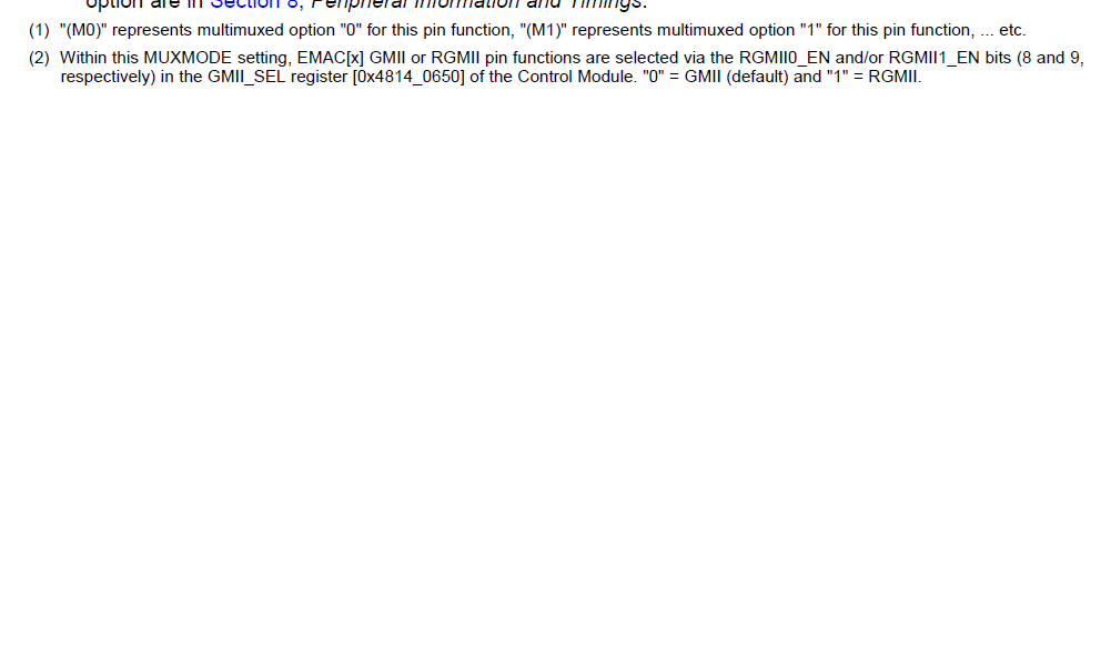
InTable 4-2. XIP (on GPMC) Boot Options there are two terms used (M0) & (M1) in the first column.

Can anyone pls clarify  the meaning of these.


Thanks in advance.

/Abhishek/

  • Hi Abhishek,

    It is in DS page 159.

  •  


    Would be nice to have some explanation of M0 and M1.

    Datasheet do not tell anything.

    Table 4-2 is not clear how to read this option M0, M1. Would be nice to know which DSP pins should be use with option M0 and which with option M1?


    Address assignment */GPMC_A[1:12]/* (M0) / */GPMC_A[1:12]/* (M1)


    For example: what should be done to use pins T23, H26……….., and when pins J28, K27, M24 can be used?

    I like to use pins T23-GPMC_A[1], H26-GPMC_A[2]……… what should be done to boot the DSP using this pins assignment?  

    What is the meaning of the DEFAULT in this table?

     AD