This thread has been locked.

If you have a related question, please click the "Ask a related question" button in the top right corner. The newly created question will be automatically linked to this question.

AM623: M4F timers - Counter Compare

Part Number: AM623
Other Parts Discussed in Thread: SYSCONFIG

Tool/software:

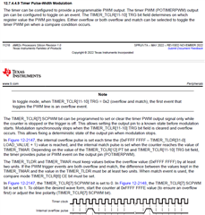
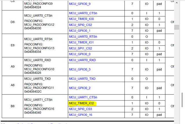
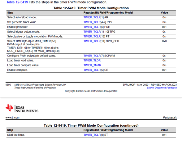
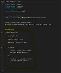
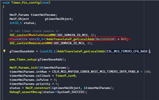
I am creating a fast output interface with the M4F, and I need both PWM and PTO signals. I was thinking about using counter compare for both, until I came across both APIs, both for timers and EPWM. But that's the problem, my demand requires that I use pure timers, without the EPWM modules to generate the PTO. EPWM will be reserved for PWM outputs. I checked the timer APIs and there is no function containing compare. By chance, there is this compare functionality but it has not yet been mapped in the API or generating the signals through the use of the overflow flag to toggle I/O at the determined frequency?

In this case, also referring to EPWM, I would be grateful if you could give a little insight into the relationship between the cycle time of a PWM, since, in the API, there are no functions like "Start_EPWM" or "Stop_EPWM", which left me a bit confusing, as it deviates from the conventional. What would be the option to start the cycle and end it? All the examples I tested led to the situation: the signal is born with the execution of the code and is never extinguished, continuing as long as the firmware on the M4F.

Yours sincerely,
Rafael Volkmer

  • Hi Rafael, could you explain me how you are planning to use "Counter Compare"?. As you mentioned, I don't see either a specific API for counting in our KERNEL DPL CLOCK module. So, you would probably need to use EPWM for Counter/Compare.


    From MCU-SDK example (I checked epwm_duty_cycle_am62x-sk-lp_m4fss0-0_freertos_ti-arm-clang) it seems to me we start/stop EPWM by enabling/disabling Event-trigger submodule.

    Links to online AM62x MCU SDK User Guide:

    AM62x MCU+ SDK: EPWM Duty Cycle (ti.com)

    AM62x MCU+ SDK: EPWM (ti.com)

    Thank you,

    Paula

  • Hello!

    Basically, I need to make a pulse train output, where I will receive information on how many pulses I should generate at each frequency and, after finishing the determined number of pulses, I change the frequency and generate another number of pulses, all with a constant duty cycle of 50%. All this with the same signal. As exemplified in the diagram below:

    EPWM modules are already being used to make PWM outputs, and I believe we will not be able to change that. The intention was to be able to formulate this algorithm based on the output compare feature, where the timer count would increase and, when it reached a certain level, before the overflow, it would generate an event, thus simulating the rising and falling edges and forming a signal during a complete timer counting cycle, ending in its overflow. I don't know if it was necessarily clear.

    Looking at the EPWM libraries, I noticed that they work this way too, with comparison values. I asked myself if I wouldn't be able to do this with a feature like this within the M4F timers, or if I would have to resort to alternative ways. If not, do you have any suggestions on what direction to take?

    Thank you very much,
    Rafael Volkmer

  • Hi Rafael, please allow me some time to check this. I will come back to you next week

    thank you,

    Paula

  • My specification for this specific output would be:

  • Hi Rafael, I am trying to see internally with some colleagues if there is any other option

    thank you,

    Paula

  • Hello! Another thing, about this example here: AM62x MCU+ SDK: EPWM Duty Cycle (ti.com)

    Was it supposed to, after the 60s passed, the EPWM signal turn off?

  • Correct, from AM62x MCU+ SDK User Guide we have:

    EPWM Duty Cycle

    • Configures ePWM0 to generate a 1KHz signal with 25% duty cycle for 60 seconds.

    AM62x MCU+ SDK: EPWM Duty Cycle (ti.com) 

    thanks,

    Paula

  • In my tests running this example, I had a pwm that never stopped running. I've made some small changes, including moving to a bare metal environment and not RTOS and, here the comparison of the two signals on pin 24 of the devkit am623 io expander (encapsulally ALW).

    The two tests recorded and compared:

    www.youtube.com/watch

  • Hello Rafael,

    For your requirement, I wanted to suggest going with the ECAP module on M4F core, but unfortunately, this is also not supported on M4F core.

    So, we need to go with Timer + GPIO.  Already, there is time interrupt that can be generated from the system config as per your requirement and you  need to  split  an ISR routine in 3 states.

    State 0 → idel state which will drive the GPIO low and will monitor no of pulses input  and frequency request. Based on this input, your states will be changed .

    I am sharing generic code based on the above example you can modify according to your, use case.

    Actually this is one of the method to achieve your requirement .

    ISR routine : 


    switch(statevariabel)
    
    {
    
    case 0 :
               GPIO_LOW; 
               if(Frequency_change)
               {
                  Frequency_change = 0x00;
                  state =2;
               }
               elseif(No_of_Pulses_Request)
               {
                   No_of_Pulses_Request = 0x00;
                  state = 1;
               }
               else
               {
                  state = 0;
               }
    
               break;
        case 1 :          
        {
            Toggle ^= 0x01;
    
          if(Toggle)
          {
            GPIO_HIGH;
          }
          else
          {
            GPIO_LOW;
            count++;
            if(count>=NO_OF_PULSES)
            {
               GPIO_LOW; 
               state = 0;
               Toggle =0x00;
            }
          }
          break;
    
        }  
    
    
        case 2 : 
         set to new time period in the Timer register ;
        state = 0;
        break;
    
        default :
        GPIO_LOW;
        Break;
    
    
    }

    Regards,

    Anil.

  • But what about the timers here? I saw this diagram and descriptions of features in the AM623 reference manual and found this information, however, without abstractions for them. Is there any example or something similar related to this?

  • Hi Rafael, let us check and come back to you

    thanks

    Paula

  • Hi Rafael, 

    Yes, it is possible with Timer PWM as well. But, in our MCU+SDK, we use it for timer purposes.

    But, for your requirement generate the PWM signal frequency with a 50% duty cycle is possible and remaining functionality, like controlling no of pulses and frequency changes and driving pwm low or high based on your requirement should be controlled by you.

    I can try to provide steps for how to do itSo, that you can try at your side and let us know the status .

    Regards,

    Anil.

  • Hello Rafael,

    I have tried the below steps to generate PWM  from the Timer Module.

    1. Each timer has a single pin and it can be used in PWM or CAP mode. 

    Currently, in MCU+SDK, it does not support this pin configuration.

    So, you need to configure based on timer and pins from the datasheet.

    I have used MCU Timer 2 and B8 pin is available on AM64X EVM for testing purposes. So, I have used this pin.

        Pinmux_PerCfg_t Timer_pin_Cfg[] =
        {
           {
               PIN_MCU_UART1_CTSN,
               ( PIN_MODE(1)  | PIN_PULL_DISABLE )
           },
    
               {PINMUX_END, PINMUX_END}
        };
    
    
        Pinmux_config(Timer_pin_Cfg, PINMUX_DOMAIN_ID_MCU);

    2. To generate PWM, either we can go with the overflow method and the match method. In current your case the overflow method is fine.

    So, I have enabled the overflow method.

    3. I have followed the steps below.

    4. When you change frequency from old to a new one, make sure that you should drive the PWM low and stop the timer and reload the new frequency and counter and next start the timer for smooth frequency update.

    Here is an example. I have updated for your reference.

    1614.hello_world_am64x-evm_m4fss0-0_nortos_ti-arm-clang.zip

    NOTE : I have tested this example on AM64X M4F  core and the same code can work on R5F or M4F core on AM64X devices and AM62X devices.

    You can just copy and paste  main.c and hello world.c files to AM62X/AM64X R5F or M4F Projects .

    Next, change Pin and Timer Base Register addresses based on your pin and Timer selection and compile the project  and load the project  from CCS.

    Regards,

    Anil.

  • Can i just throw this files at empty project example on MCU+SDK and configure the sysconfig file here, right?

    "this files" i mean main.c and hello_world.c

  • Hello Rafael,

    Yes, you are correct. I have created an example on the hello_World project., you need to copy main. C and hell_world.c file functions in to  your project.

    I have not configured any system config since don't support this feature from system cfg and everything I have done manually .

    Regards,

    Anil.

  • Can you please tell me what calculation was set to adjust the frequency to 5khz and the duty to 50%? I am adjusting the frequencies and getting a gap in what I want

  • Hello Rafael,

    In the above test code, I have created to drive PWM low for 10 samples, and please look at the image below for your reference.

    Actually, in your case, you need to drive PWM low. So, I have added the same logic to the code.

    If you don't need it, please comment the code from 100 to 123 lines and modify code according to your requirements.

    To change frequency, please update the macro value below and every time you will get a 50%duty value.

    The timer input clock is 25MHz and you need a 5KHz (0.2msec) signal.

    TON  = 0.1msec and TOFF = 0.1msec .

    So, you need to configure the macro below as 

    #define TIMER_ON_PERIOD ( give count value in usec * 1000) //in Nsec .
    Now, PWM pin will google for every 100usec .
    #define TIMER_ON_PERIOD (100 * 1000) 

    Please let us if you face any issues .

    Regards,

    Anil.

  • I'm trying to adapt the function to pass the frequency and duty cycle to the PWM signal, however, without success, due to the nature of the calculation. Do you have any ideas? And, also, there is a maximum frequency for the PWM signal, because I need to reach 200khz.

    im trying something like that

  • Hello Rafael,

    I am not sure which duty you are trying ? Is not 50% duty ?

    I have added my comments above that this example can work for 50% duty if you need other than 50% duty. In the same example, you need to enable TMAR configurations as well. But, in your experiment you said that you need only 50% duty .

    For 200Khz signal, what is the macro value you are passing ?

    #define TIMER_ON_PERIOD  ?

    Regards,

    Anil.

  • for the PTO, 50% duty cycle is fine, however, I also need to develop a PWM interface with the same peripherals. The need to change the duty cycle in a scale of 1% - 99% is there. In this case, for 200khz I used this, and works nice:

    #define TIMER_ON_PERIOD (2500 * 1000)
    in this case, frequency is not a problem, just duty cycle..
  • Now, the frequency is a problem

    When i get this, generate a 4khz wave: 

  • Hello Rafael,

    Please look at the image below.

    The PWM is generated based on either overflow or overflow and match type.

    Currently, I have enabled with overflow.

    So, frequency and duty values are purely based on overflow value.

    For example, if you need a 10% duty cycle with 1 KHz frequency.

    TON = 10% * 1K and TOFF = 90% * 1K. So, in this time period you need to change  for every time in the Timer ISR routine .

    If you need to 200KHz with different duties from 1% to 99%.

    We are feeding a 25MHz clock to the time without any scaling.

    For 1% duty, TON = 1% of 200KHZ and the remaining TOFF = 99% of 200KHz time should be loaded.

    So, for every time you need to load the TON and TOFF periods in the ISR routine, this way you can achieve different duties and frequencies.

    There is a TIMER_MAR register to see if this register can be used for duty and the over overflow timer can be used for frequency and try with this method also.

    Regards,

    Anil.

  • Hello!

    Currently, my code is like this. I studied a little about how TMAR works:

    #define USR_TIMER_IRQ_EOI           (0x20u)
    #define USR_TIMER_IRQ_STATUS_RAW    (0x24u)
    #define USR_TIMER_IRQ_STATUS        (0x28u)
    #define USR_TIMER_IRQ_INT_ENABLE    (0x2Cu)
    #define USR_TIMER_IRQ_INT_DISABLE   (0x30u)
    #define USR_TIMER_TCLR              (0x38u)
    #define USR_TIMER_TCRR              (0x3cu)
    #define USR_TIMER_TLDR              (0x40u)
    #define USR_TIMER_TMAR              (0x44u)
    #define USR_TIMER_OVF_INT_SHIFT     (0x1)
    
    void PWM_timSetup(uint32_t baseAddr, uint32_t frequency, uint32_t duty)
    {
        volatile uint32_t *addr;
        uint32_t ctrlVal;
        uint32_t timerCycles;
        uint32_t countVal;
        uint64_t tmarValue;
    
        TimerP_stop(baseAddr);
        TimerP_clearOverflowInt(baseAddr);
    
        timerCycles = 25000000U / frequency ;
    
        countVal = 0xFFFFFFFFU - timerCycles + 1U;
    
        tmarValue = countVal + ( timerCycles * (duty/ 100U) );
    
        ctrlVal = 0;
    
        addr = (volatile uint32_t *)(baseAddr + USR_TIMER_TCLR);
        CSL_REG32_WR(addr, ctrlVal);
    
        ctrlVal = (1 << 10U) | (1 << 12U) | (1 << 1);
        CSL_REG32_WR(addr, ctrlVal);
    
        addr = (volatile uint32_t *)(baseAddr + USR_TIMER_TLDR);
        CSL_REG32_WR(addr, countVal);
    
        addr = (volatile uint32_t *)(baseAddr + USR_TIMER_TMAR);
        CSL_REG32_WR(addr, tmarValue);
    }

    However, still without success. I don't know if I misinterpreted something in the documentation.

  • Hello Rafael,

    Can you please try the code below and I have verified at 200KHz with 1% duty and 99% and all working as expected.

    You need to check for all frequencies and duties and I have not verified for all frequencies.

    You need to pass two parameters, one for frequency and duty.

    For frequency, you need to pass time in nsec.

    For example, you need a 200KHz frequency and the time period is 5usec and this value needs to convert to nsec values.

    So, you need to pass 

     #define TIMER_PERIOD (5000) //in Nsec

    and duty values from 0 to 100%

    If duty is 50% duty, then go ahead with the overflow method. 

    If duty is other than 50%, then you go ahead with overflow and match mode.

    For 0% duty, either you can set no trigger method or set the SCPWM bit  as low. 

    For 100% duty, you can set a pin as high with the help of SCPWM bit as high. 

    I have seen one observation while continuously  writing TCLR register is not allowing to update new writes operation .

    We need to check whether this operation is completed  or not before proceeding  for new change in TCLR register .

    I am assume that this might be problem with Core Clock and Timer interface clock will be different .I can confirm .

    4101.hello_world_am64x-evm_m4fss0-0_nortos_ti-arm-clang.zip

    Regards,

    Anil.

  • If i just start the code by code composer, it provides me a 50% duty 1khz. But, if i build step by step, the duty is working but the frequency is 3khz. I just change my timer for MCU_TIMER3 and TIMER_IO3. Any idea where is the problem?

  • With the values 45 for duty and 5000 for period, i got this (Just debugging step by step):

    Without being step by step, I only achieve this in 100% of situations:

  • Hello Rafael,

    Please look at the image below and I got frequency 200KHz and duty is 44%.

    I am not sure why you are having strange behavior.

    Did you integrate my changes into your application ?

    How are you loading an application from CCS or Linux ?

    Can you do POR or warmest the devices and load the application and still see if you have an issue ?

    How did you feed duty and frequency values in application ? You are changing them frequently  in the code or only calling for one time.

    Regards,

    Anil.

  • Hello! The only modification i made is the timer instance:

    The code is the same that you give to me.

    Im loading my aplication by CCS.

  • Still my code run properly only step by step debug on CCS.

  • Hello Rafael,

    The first problem is that your application is not properly selecting the correct clock for Timer 3.

    For the Timer 3 clock selection we need to use the address below.

    So, you need to change the red-colored with to the 0x450806C address.

    Still my code run properly only step by step debug on CCS.

    Yes, I have also seen the same issues. We need to enable synchronization between Core and Timer modules while writing in to Timer Registers .

    I have seen some registers are there to synchronize between writing operations of each Timer Register.

    So, we need to check for each write writing operation whether the writing operation is done or not .

    Now, you can go ahead with the single step execution from CCS to update values in to TCLR registers .

    Now, you can see whether you are able to get the proper frequency and duty values with the above code .

    Later, we will work on how to solve this issue .

    Regards,

    Anil.

  • I made some modifications, but nothing that changed the logic. I'm still stuck on a duty_cycle that works and a frequency of 3hz to 5000. I tested it on my home setup at night and I managed to reach 200khz, however, on the company setup, only 3hz. I don't know exactly what's wrong.

    #include <stdio.h>
    #include <kernel/dpl/DebugP.h>
    #include "ti_drivers_config.h"
    #include "ti_drivers_open_close.h"
    #include "ti_board_open_close.h"
    
    /* ----------- TimerP ----------- */
    #include <kernel/dpl/TimerP.h>
    
    
    void TimerP_isr0(void *args);
    void pwm_Timer_setup(uint32_t baseAddr);
    
    
    extern uint32_t gTimerBaseAddr;
    
    volatile uint32_t  noofsamples = 0U;
    
    #define USR_TIMER_IRQ_EOI           (0x20u)
    #define USR_TIMER_IRQ_STATUS_RAW    (0x24u)
    #define USR_TIMER_IRQ_STATUS        (0x28u)
    #define USR_TIMER_IRQ_INT_ENABLE    (0x2Cu)
    #define USR_TIMER_IRQ_INT_DISABLE   (0x30u)
    #define USR_TIMER_TCLR              (0x38u)
    #define USR_TIMER_TCRR              (0x3cu)
    #define USR_TIMER_TLDR              (0x40u)
    #define USR_TIMER_TMAR              (0x4Cu)
    
    #define USR_TIMER_OVF_INT_SHIFT     (0x1)
    
    #define USR_TIMER_MATCH_INT_SHIFT     (0x0)
    
    
    #define PWM_TCLR_SCPWM_BIT_MSK     (0x7U)
    
    
    #define TIMER_PERIOD (5000) //in Nsec
    
    #define TIMER_INPUT_CLOCK     (25000000UL)
    
    #define PWM_DUTY_0_PERCENT   0U
    
    #define PWM_DUTY_100_PERCENT 100U
    
    #define PWM_DUTY_50_PERCENT  50U
    
    #define USR_PWM_DUTY_PERCENT_CONFIG  90U
    
    
    void Pwm_SetPeriodAndDuty(uint64_t Period, uint8_t DutyCycle);
    
    
    volatile uint8_t Test_Variable = 0U;
    
    volatile uint64_t Test_Frequency = 0U;
    volatile uint8_t Test_Duty = 0U;
    
    void hello_world_main(void *args)
    {
        /* Open drivers to open the UART driver for console */
        Drivers_open();
        Board_driversOpen();
        Pwm_SetPeriodAndDuty(TIMER_PERIOD,USR_PWM_DUTY_PERCENT_CONFIG);
    
        TimerP_start( gTimerBaseAddr );
    
        while(1)
        {
    //        switch(Test_Variable)
    //        {
    //          case 0U:
    //              Pwm_SetPeriodAndDuty(TIMER_PERIOD,PWM_DUTY_0_PERCENT);
    //          break;
    //          case 1U:
    //              Pwm_SetPeriodAndDuty(TIMER_PERIOD,PWM_DUTY_50_PERCENT);
    //          break;
    //          case 2U:
    //              Pwm_SetPeriodAndDuty(TIMER_PERIOD,PWM_DUTY_100_PERCENT);
    //          break;
    //          case 3U:
    //              Pwm_SetPeriodAndDuty(Test_Frequency,PWM_DUTY_50_PERCENT);
    //          break;
    //          case 4U:
    //              Pwm_SetPeriodAndDuty(Test_Frequency,Test_Duty);
    //          break;
    //          default :
    //              Pwm_SetPeriodAndDuty(TIMER_PERIOD,PWM_DUTY_0_PERCENT);
    //           break;
    //        }
        }
        DebugP_log("Hello World!\r\n");
    
        Board_driversClose();
        Drivers_close();
    }
    
    void pwm_Timer_setup(uint32_t baseAddr)
    {
        volatile uint32_t *addr;
        volatile uint32_t ctrlVal = 0x00;
        volatile uint32_t countVal, reloadVal;
        volatile uint64_t timeInNsec, inputClkHz, timerCycles;
    
        volatile uint8_t enableOverflowInt = FALSE;
    
        /* stop timer and clear pending interrupts */
        TimerP_stop(baseAddr);
        TimerP_clearOverflowInt(baseAddr);
    
        timeInNsec = (uint64_t)TIMER_PERIOD / 2U;
    
        inputClkHz = 25000000U / 1U;
        timerCycles =  ( inputClkHz * timeInNsec ) / 1000000000U;
    
        /* if timerCycles > 32b then we cannot give accurate timing */
        DebugP_assert( timerCycles < 0xFFFFFFFFU );
    
        /* calculate count and reload value register value */
        countVal = 0xFFFFFFFFU - (timerCycles - 1U);
    
        /* keep reload value as 0, later if is auto-reload is enabled, it will be set a value > 0 */
        reloadVal = countVal;
    
        /* calculate control register value, keep timer disabled */
        ctrlVal = 0;
    
        /* set timer control value */
        addr = (volatile uint32_t *)(baseAddr + USR_TIMER_TCLR);
        CSL_REG32_WR(addr,ctrlVal);
    
    
        ctrlVal =  ( (1<<10U) | (1<<12U) | (1<<1) ); //Trigger on overflow, Toggle, enable Auto Reload Mode
        CSL_REG32_WR(addr,ctrlVal);
    
    
        /* set reload value */
        addr = (volatile uint32_t *)(baseAddr + USR_TIMER_TLDR);
        CSL_REG32_WR(addr,reloadVal);
    
    
        /* set timer count value */
        addr = (volatile uint32_t *)(baseAddr + USR_TIMER_TCRR);
        CSL_REG32_WR(addr,countVal);
    
        /* enable/disable interrupts */
        if(enableOverflowInt == TRUE)
        {
            /* enable interrupt */
            addr = (volatile uint32_t *)(baseAddr + USR_TIMER_IRQ_INT_ENABLE);
            ctrlVal = (0x1U << USR_TIMER_OVF_INT_SHIFT)| (0x1U << USR_TIMER_MATCH_INT_SHIFT);
            CSL_REG32_WR(addr,ctrlVal);
    
        }
        else
        {
            /* disable interrupt */
            addr = (volatile uint32_t *)(baseAddr + USR_TIMER_IRQ_INT_DISABLE);
            ctrlVal = (0x1U << USR_TIMER_OVF_INT_SHIFT) |  (0x1U << USR_TIMER_MATCH_INT_SHIFT);
            CSL_REG32_WR(addr,ctrlVal);
    
        }
    
    }
    
    void Pwm_SetPeriodAndDuty(volatile uint64_t Period_count, volatile uint8_t DutyCycle)
    {
    
        volatile uint32_t regVal;
        volatile uint64_t Period;
        volatile uint32_t absolute_dutyCycle;
        volatile uint32_t TLDR_VALUE             =        0U;
        volatile uint32_t TMAR_VALUE             =        0U;
    
        /* Handle boundary conditions of 0% */
        /* Handle boundary conditions of 100% */
        if (PWM_DUTY_0_PERCENT == DutyCycle)
        {
            /* For 0% Dutycycle Output is inverse of configured polarity parameter
             * disable timer */
            TimerP_stop( gTimerBaseAddr );
    
    
            regVal = CSL_REG32_RD(gTimerBaseAddr + USR_TIMER_TCLR);
            regVal &= (~((uint32_t)1U<< PWM_TCLR_SCPWM_BIT_MSK));
            CSL_REG32_WR((gTimerBaseAddr + USR_TIMER_TCLR), regVal);
        }
        else if (PWM_DUTY_100_PERCENT == DutyCycle)
        {
            /* For 100% Dutycycle Output is equal configured polarity parameter
             * disable timer */
            TimerP_stop( gTimerBaseAddr );
    
            regVal = CSL_REG32_RD(gTimerBaseAddr + USR_TIMER_TCLR);
            regVal |= ((uint32_t)1U<< PWM_TCLR_SCPWM_BIT_MSK);
            CSL_REG32_WR((gTimerBaseAddr + USR_TIMER_TCLR), regVal);
        }
        else
        {
    
            regVal = CSL_REG32_RD(gTimerBaseAddr + USR_TIMER_TCLR);
            regVal &= ~((uint32_t)1U<< PWM_TCLR_SCPWM_BIT_MSK);
            CSL_REG32_WR( (gTimerBaseAddr + USR_TIMER_TCLR) , regVal);
    
            Period =  (  ( TIMER_INPUT_CLOCK * Period_count ) / 1000000000U );
    
            /* Calculating absolute duty cycle in ticks */
            absolute_dutyCycle = Period - ( (Period * DutyCycle )/ 100U );
            /* Calculating Reload and Compare register values  */
            if (PWM_DUTY_50_PERCENT == DutyCycle)
            {
                /* set timer control value */
                regVal = CSL_REG32_RD(gTimerBaseAddr + USR_TIMER_TCLR);
                regVal &= ~( (1<<11U) | (1<<6U)  );
                regVal |= ( (1<<10U) );
                CSL_REG32_WR( (gTimerBaseAddr + USR_TIMER_TCLR),regVal);
    
                TLDR_VALUE = (Period) / 2U;
    
                /* set timer Match value */
                CSL_REG32_WR( (gTimerBaseAddr + USR_TIMER_TMAR),0U);
            }
            else
            {
                /* set timer control value */
                regVal = CSL_REG32_RD(gTimerBaseAddr + USR_TIMER_TCLR);
                regVal &= ( ~ (1<<10U) );
                regVal |= ( (1<<11U) | (1<<6U) );
    
                TLDR_VALUE = (Period);
    
                TMAR_VALUE = 0xFFFFFFFFU - absolute_dutyCycle - 1U;
    
                /* set timer count value */
                CSL_REG32_WR((gTimerBaseAddr + USR_TIMER_TMAR),TMAR_VALUE);
                CSL_REG32_WR((gTimerBaseAddr + USR_TIMER_TCLR),regVal);
    
            }
    
            TLDR_VALUE = 0xFFFFFFFFU - (TLDR_VALUE - 1U);
    
            /* set timer count value */
            CSL_REG32_WR((gTimerBaseAddr + USR_TIMER_TCRR),TLDR_VALUE);
    
            /* set reload value */
            CSL_REG32_WR((gTimerBaseAddr + USR_TIMER_TLDR),TLDR_VALUE);
    
            return;
        }
    }


    /*
     *  Copyright (C) 2018-2021 Texas Instruments Incorporated
     *
     *  Redistribution and use in source and binary forms, with or without
     *  modification, are permitted provided that the following conditions
     *  are met:
     *
     *    Redistributions of source code must retain the above copyright
     *    notice, this list of conditions and the following disclaimer.
     *
     *    Redistributions in binary form must reproduce the above copyright
     *    notice, this list of conditions and the following disclaimer in the
     *    documentation and/or other materials provided with the
     *    distribution.
     *
     *    Neither the name of Texas Instruments Incorporated nor the names of
     *    its contributors may be used to endorse or promote products derived
     *    from this software without specific prior written permission.
     *
     *  THIS SOFTWARE IS PROVIDED BY THE COPYRIGHT HOLDERS AND CONTRIBUTORS
     *  "AS IS" AND ANY EXPRESS OR IMPLIED WARRANTIES, INCLUDING, BUT NOT
     *  LIMITED TO, THE IMPLIED WARRANTIES OF MERCHANTABILITY AND FITNESS FOR
     *  A PARTICULAR PURPOSE ARE DISCLAIMED. IN NO EVENT SHALL THE COPYRIGHT
     *  OWNER OR CONTRIBUTORS BE LIABLE FOR ANY DIRECT, INDIRECT, INCIDENTAL,
     *  SPECIAL, EXEMPLARY, OR CONSEQUENTIAL DAMAGES (INCLUDING, BUT NOT
     *  LIMITED TO, PROCUREMENT OF SUBSTITUTE GOODS OR SERVICES; LOSS OF USE,
     *  DATA, OR PROFITS; OR BUSINESS INTERRUPTION) HOWEVER CAUSED AND ON ANY
     *  THEORY OF LIABILITY, WHETHER IN CONTRACT, STRICT LIABILITY, OR TORT
     *  (INCLUDING NEGLIGENCE OR OTHERWISE) ARISING IN ANY WAY OUT OF THE USE
     *  OF THIS SOFTWARE, EVEN IF ADVISED OF THE POSSIBILITY OF SUCH DAMAGE.
     */
    
    #include <stdlib.h>
    #include "ti_drivers_config.h"
    #include "ti_board_config.h"
    #include <kernel/dpl/HwiP.h>
    #include <kernel/dpl/TimerP.h>
    #include <drivers/pinmux.h>
    
    void hello_world_main(void *args);
    void Timer_Pin_config(void);
    
    uint32_t gTimerBaseAddr = 0U;
    
    extern void pwm_Timer_setup(uint32_t baseAddr);
    
    int main(void)
    {
        System_init();
        Board_init();
        Timer_Pin_config();
    
        hello_world_main(NULL);
    
        Board_deinit();
        System_deinit();
    
        return 0;
    }
    
    void Timer_Pin_config(void)
    {
        TimerP_Params timerParams;
    
        /* set timer clock source */
        SOC_controlModuleUnlockMMR(SOC_DOMAIN_ID_MCU, 0);
        *(volatile uint32_t*)AddrTranslateP_getLocalAddr(0x4508068U) = 0x0;
        SOC_controlModuleLockMMR(SOC_DOMAIN_ID_MCU, 0);
    
        gTimerBaseAddr = (uint32_t)AddrTranslateP_getLocalAddr(CSL_MCU_TIMER3_CFG_BASE);
    
        TimerP_Params_init(&timerParams);
        timerParams.inputPreScaler = 1U;
        timerParams.inputClkHz     = 25000000U;
        timerParams.periodInNsec   = 0U;
        timerParams.oneshotMode    = 0U;
        timerParams.enableOverflowInt = 0U;
        timerParams.enableDmaTrigger  = 0U;
        TimerP_setup(gTimerBaseAddr, &timerParams);
    
        pwm_Timer_setup(gTimerBaseAddr);
    
        Pinmux_PerCfg_t Timer_pin_Cfg[] =
        {
           {
               PIN_MCU_MCAN1_RX,
               ( PIN_MODE(1)  | PIN_PULL_DISABLE )
           },
    
                {PINMUX_END, PINMUX_END}
        };
    
    
        Pinmux_config(Timer_pin_Cfg, PINMUX_DOMAIN_ID_MCU);
    }
    

  • I made some modifications, but nothing that changed the logic. I'm still stuck on a duty_cycle that works and a frequency of 3hz to 5000. I tested it on my home setup at night and I managed to reach 200khz, however, on the company setup, only 3hz. I don't know exactly what's wrong

    Hello Rafel,

    If the timer clock selection is other than 25MHz, then the PWM frequency will be different according to the 5000 Counter value for 200KHz.

    So, please confirm did you change the clock selection address in both your setups or not ?

    For the Timer 3 clock selection we need to use the address below.

    So, you need to change the red-colored with to the 0x450806C address.

    Even if you change the clock selection address and does not come proper PWM signal frequency, then check the TMAR and TLDR registers are properly loaded with your input or not.

    I have verified that I am able to get 200KHz from 1% to 99% duty and only issue with the TCLR registers need some more time to update it s values .

    Regards,

    Anil.

  • Its work with some small mpdifications for my device! I thing the problem is with my setup at work. In my personal computer, its all right.

    Here is the function I made to wait the TCLR values be loaded before runing the code properly, if someone have the same problem:

    /* Timers Control Function */
    static FastIO_status_t FastIO_timerControl(uint32_t timer_addr)
    {
        FastIO_status_t status_out  = PWM_SUCESS;;
    
        uint32_t TCLR_val_write     = CLEAR;
        uint32_t TCLR_val_read      = CLEAR;
    
        uint32_t TCLR_write_pending = CLEAR;
    
        volatile uint32_t *TCLR_ptr;
        volatile uint32_t *TWPS_ptr;
    
        uint32_t sucess_flag        = CLEAR;
    
        TCLR_ptr = (volatile uint32_t *)(timer_addr + USR_TIMER_TCLR);
        TWPS_ptr = (volatile uint32_t *)(timer_addr + USR_TIMER_TWPS);
    
        TCLR_val_write = 
        ( 
            (0 << 14u) |  // PWM OUTPUT: MCU_TIMER03 -> MCU_TIMER_IO3 (D4 | PIN 11)
            (1 << 12u) |  // Toggle on a event
            (1 << 11u) |  // Event on MATCH and OVERFLOW
            (0 << 10u) |  // Event on MATCH and OVERFLOW
            (1 << 7u)  |  // Default value at PWM pin is high
            (1 << 6u)  |  // Enable Compare Feature
            (1 << 5u)  |  // Disable Prescaler
            (1 << 1u)  |  // Auto Reload mode
            (0 << 0u)     // Stop Timer
        );
    
        CSL_REG32_WR((timer_addr + USR_TIMER_TCLR), TCLR_val_write);
    
        TCLR_val_read = CSL_REG_RD(TCLR_ptr);
    
        while( !(sucess_flag) )
        {
        
            switch (TCLR_val_read)
            {
                case EXPECTED_TCLR:
    
                    sucess_flag = SET;
    
                        break;
    
                default:
    
                    do
                    {
                        CSL_REG32_WR( (timer_addr + USR_TIMER_TCLR), TCLR_val_write);
    
                        TCLR_write_pending = CSL_REG_RD(TWPS_ptr);
                        
                    } while ( (TCLR_write_pending & TCLR_BIT_MASK) );
    
                        break;
            }
        }
    
        return status_out;
    }

  • Hello Rafael,

    Thanks for your update.

    The above fix seems OK, but I have added similar logic to my test code. Please use it for a proper fix .

    Hello Future readers ,

    Please consider below points while using PWM in your application with the Timer module .

    1. When changing duty from 100% to other than 0% duty , make sure that SCPWM signal should be low . For this , user need to call Pwm_SetPeriodAndDuty API  with 0% duty then feed user duty values, otherwise user may get different duty values  .

    2. Not enabled interrupts 

    3. Duty resolution is 1%

    4. By default 25MHZ clock is feeding to Timer Module and prescaler are disabled.

    5. Call Pwm_SetPeriodAndDuty API , if any change in frequency and duty for only one time..

    6. The Application is available on AM64X M4F and it can be used for R5F or M4F on AM62X and AM64X  as well .

    Just update Timer PWM pin , Timer Clock selection address and Timer instance as per user Timer selection .

    2671.hello_world_am64x-evm_m4fss0-0_nortos_ti-arm-clang.zip

    Regards,

    Anil.