Other Parts Discussed in Thread: SYSCONFIG, CCSTUDIO
Tool/software:
Dear TI Support,
We are facing an issue with our custom J784S4 board for which we made a SysConfig tool configuration and created a custom board library as per this How-To: Create board library with custom name. This was done in order to not modify the pinmux configuration of the j784s4_evm target since the Evaluation Kit is still in use and the new custom target is basically just a copy of the j784s4_evm target with the only difference being the pinmux configuration generated using the Sysconfig tool.
However, when calling Board_init with parameters BOARD_INIT_UNLOCK_MMR | BOARD_INIT_PINMUX_CONFIG | BOARD_INIT_MODULE_CLOCK, we notice that none of the configured GPIO output pins are actually being set to the desired output levels using Dio_WriteChannel.
A part of our code in the R5F is using the manual pin mux settings for the CAN transceivers from the mcusw CAN profiling demo. So, since we have this in our code, actually GPIO pins WKUP_GPIO0_0 and WKUP_GPIO0_69 are set correctly as output pins.
Here is the code which does that:
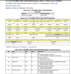
regVal = 0x08050007U;
CSL_REG32_WR(CSL_WKUP_CTRL_MMR0_CFG0_BASE + CSL_WKUP_CTRL_MMR_CFG0_PADCONFIG48, regVal);
/* Set Pin direction to output */
regVal = CSL_REG32_RD(CSL_WKUP_GPIO0_BASE + 0x10U);
regVal &= (~(1U << 0x0U));
CSL_REG32_WR(CSL_WKUP_GPIO0_BASE + 0x10U, regVal);

{ ... }

regVal = 0x08050007U;
CSL_REG32_WR(CSL_WKUP_CTRL_MMR0_CFG0_BASE +
    CSL_WKUP_CTRL_MMR_CFG0_PADCONFIG42, regVal);
/* Set Pin direction to output */
regVal = CSL_REG32_RD(CSL_WKUP_GPIO0_BASE + 0x60U);
regVal &= (~(1U << 0x05U));
CSL_REG32_WR(CSL_WKUP_GPIO0_BASE + 0x60U, regVal);
However, since the hardware design is different on the custom board we now need WKUP_GPIO0_10 and WKUP_GPIO0_69 as output pins for EN and STB for the CAN transceiver and of course several others.
So, while trying to debug why the GPIO directions are not set I've compared the register values that are written to the registers in the code mentioned before with the register values that are written by the function Board_pinmuxUpdate which is called by Board_init when the BOARD_INIT_PINMUX_CONFIG parameter is passed.
I noticed that the manual code writes 0x8050007u to the registers vs the "Board_init way" writing only 0x0050007u to the output registers. Where does this difference come from and does it have any relevance?
Also, the part of the code above which is supposed to set the output direction
/* Set Pin direction to output */
regVal = CSL_REG32_RD(CSL_WKUP_GPIO0_BASE + 0x10U);
regVal &= (~(1U << 0x0U));
CSL_REG32_WR(CSL_WKUP_GPIO0_BASE + 0x10U, regVal);
does not seem to be replicated anywhere inside Board_init().
I'm not sure which exact register the above code writes there, but I figured out that if I manually modify a bit in register WKUP_GPIO0.MEM_DIR01 in CCStudio then afterwards I'm actually able to set that pins output level using Dio_WriteChannel.
Can you please help me to understand why the GPIO pins are not set as output pins using Board_init and whether the approach with the custom board library and Sysconfig tool is the "TI intended" way? If yes, did we miss something in the configuration or some other step on the way to make this work?
I've attached our SysConfig configuration for you to check. We are using SDK 9.2, CCStudio 12.4 and currently the board is initialized by GEL files only. Might there be actually the problem?
Thanks in advance!
Best regards,