Tool/software:
I am having trouble running Hardware System Trace on our custom target h/w to perform various hardware analyses, e.g. "Memory Throughput Analysis", etc.
I have a custom target system that has 4 C6678s.
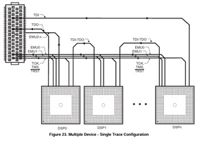
I have created a Target Configuration as follows using the BHUSB56v2 System Trace connecting to 4 C6678s in the same JTAG scan chain of our custom h/w.
Using this Target Configuration I can successfully connect and run source level debugging on all 4 C6678 DSPs and each of their 8 cores, i.e. all 32 cores.
<?xml version="1.0" encoding="UTF-8" standalone="no"?>
<configurations XML_version="1.2" id="configurations_0">
<configuration XML_version="1.2" id="Blackhawk XDS560v2-USB System Trace Emulator_0">
        <instance XML_version="1.2" desc="Blackhawk XDS560v2-USB System Trace Emulator_0" href="connections/BH-XDS560v2-USB_Connection.xml" id="Blackhawk XDS560v2-USB System Trace Emulator_0" xml="BH-XDS560v2-USB_Connection.xml" xmlpath="connections"/>
        <connection XML_version="1.2" id="Blackhawk XDS560v2-USB System Trace Emulator_0">
            <instance XML_version="1.2" href="drivers/tixds560icepick_d.xml" id="drivers" xml="tixds560icepick_d.xml" xmlpath="drivers"/>
            <instance XML_version="1.2" href="drivers/tixds560c66xx.xml" id="drivers" xml="tixds560c66xx.xml" xmlpath="drivers"/>
            <instance XML_version="1.2" href="drivers/tixds560cs_dap.xml" id="drivers" xml="tixds560cs_dap.xml" xmlpath="drivers"/>
            <instance XML_version="1.2" href="drivers/tixds560csstm.xml" id="drivers" xml="tixds560csstm.xml" xmlpath="drivers"/>
            <instance XML_version="1.2" href="drivers/tixds560etbcs.xml" id="drivers" xml="tixds560etbcs.xml" xmlpath="drivers"/>
            <platform XML_version="1.2" id="platform_0">
                <instance XML_version="1.2" desc="TMS320C6678_0" href="devices/C6678.xml" id="TMS320C6678_0" xml="C6678.xml" xmlpath="devices"/>
                <device HW_revision="1" XML_version="1.2" description="C66x core" id="TMS320C6678_0" partnum="TMS320C6678"/>
                <instance XML_version="1.2" desc="TMS320C6678_1" href="devices/C6678.xml" id="TMS320C6678_1" xml="C6678.xml" xmlpath="devices"/>
                <device HW_revision="1" XML_version="1.2" description="C66x core" id="TMS320C6678_1" partnum="TMS320C6678">
                    <router HW_revision="1.0" XML_version="1.2" desc="IcePick_E" description="ICEPick_D Router" id="IcePick_D_0" isa="ICEPICK_D">
                        <subpath desc="subpath_8" id="subpath_0">
                            <cpu HW_revision="1.0" XML_version="1.2" desc="C66xx_8" description="C66xx CPU" id="C66xx_0" isa="TMS320c66xx"/>
                        </subpath>
                        <subpath desc="subpath_9" id="subpath_1">
                            <cpu HW_revision="1.0" XML_version="1.2" desc="C66xx_9" description="C66xx CPU" id="C66xx_1" isa="TMS320c66xx"/>
                        </subpath>
                        <subpath desc="subpath_10" id="subpath_2">
                            <cpu HW_revision="1.0" XML_version="1.2" desc="C66xx_10" description="C66xx CPU" id="C66xx_2" isa="TMS320c66xx"/>
                        </subpath>
                        <subpath desc="subpath_11" id="subpath_3">
                            <cpu HW_revision="1.0" XML_version="1.2" desc="C66xx_11" description="C66xx CPU" id="C66xx_3" isa="TMS320c66xx"/>
                        </subpath>
                        <subpath desc="subpath_12" id="subpath_4">
                            <cpu HW_revision="1.0" XML_version="1.2" desc="C66xx_12" description="C66xx CPU" id="C66xx_4" isa="TMS320c66xx"/>
                        </subpath>
                        <subpath desc="subpath_13" id="subpath_5">
                            <cpu HW_revision="1.0" XML_version="1.2" desc="C66xx_13" description="C66xx CPU" id="C66xx_5" isa="TMS320c66xx"/>
                        </subpath>
                        <subpath desc="subpath_14" id="subpath_6">
                            <cpu HW_revision="1.0" XML_version="1.2" desc="C66xx_14" description="C66xx CPU" id="C66xx_6" isa="TMS320c66xx"/>
                        </subpath>
                        <subpath desc="subpath_15" id="subpath_7">
                            <cpu HW_revision="1.0" XML_version="1.2" desc="C66xx_15" description="C66xx CPU" id="C66xx_7" isa="TMS320c66xx"/>
                        </subpath>
                        <subpath desc="DAP_0" id="DAP">
                            <router HW_revision="1.0" XML_version="1.2" desc="CS_DAP_DebugSS_0" description="CS DAP Router" id="CS_DAP_DebugSS" isa="CS_DAP">
                                <subpath desc="STM_0" id="STM">
                                    <cpu HW_revision="1.0" XML_version="1.2" desc="CSSTM_1" description="CS System Trace" id="CSSTM_0" isa="TMS470R26X"/>
                                    <cpu HW_revision="1.0" XML_version="1.2" desc="TETB_STM_0" description="CS Embedded Trace Buffer" id="TETB_STM" isa="CS_ETB"/>
                                </subpath>
                            </router>
                        </subpath>
                    </router>
                </device>
                <instance XML_version="1.2" desc="TMS320C6678_2" href="devices/C6678.xml" id="TMS320C6678_2" xml="C6678.xml" xmlpath="devices"/>
                <device HW_revision="1" XML_version="1.2" description="C66x core" id="TMS320C6678_2" partnum="TMS320C6678">
                    <router HW_revision="1.0" XML_version="1.2" desc="IcePick_F" description="ICEPick_D Router" id="IcePick_D_0" isa="ICEPICK_D">
                        <subpath desc="subpath_16" id="subpath_0">
                            <cpu HW_revision="1.0" XML_version="1.2" desc="C66xx_16" description="C66xx CPU" id="C66xx_0" isa="TMS320c66xx"/>
                        </subpath>
                        <subpath desc="subpath_17" id="subpath_1">
                            <cpu HW_revision="1.0" XML_version="1.2" desc="C66xx_17" description="C66xx CPU" id="C66xx_1" isa="TMS320c66xx"/>
                        </subpath>
                        <subpath desc="subpath_18" id="subpath_2">
                            <cpu HW_revision="1.0" XML_version="1.2" desc="C66xx_18" description="C66xx CPU" id="C66xx_2" isa="TMS320c66xx"/>
                        </subpath>
                        <subpath desc="subpath_19" id="subpath_3">
                            <cpu HW_revision="1.0" XML_version="1.2" desc="C66xx_19" description="C66xx CPU" id="C66xx_3" isa="TMS320c66xx"/>
                        </subpath>
                        <subpath desc="subpath_20" id="subpath_4">
                            <cpu HW_revision="1.0" XML_version="1.2" desc="C66xx_20" description="C66xx CPU" id="C66xx_4" isa="TMS320c66xx"/>
                        </subpath>
                        <subpath desc="subpath_21" id="subpath_5">
                            <cpu HW_revision="1.0" XML_version="1.2" desc="C66xx_21" description="C66xx CPU" id="C66xx_5" isa="TMS320c66xx"/>
                        </subpath>
                        <subpath desc="subpath_22" id="subpath_6">
                            <cpu HW_revision="1.0" XML_version="1.2" desc="C66xx_22" description="C66xx CPU" id="C66xx_6" isa="TMS320c66xx"/>
                        </subpath>
                        <subpath desc="subpath_23" id="subpath_7">
                            <cpu HW_revision="1.0" XML_version="1.2" desc="C66xx_23" description="C66xx CPU" id="C66xx_7" isa="TMS320c66xx"/>
                        </subpath>
                        <subpath desc="DAP_1" id="DAP">
                            <router HW_revision="1.0" XML_version="1.2" desc="CS_DAP_DebugSS_1" description="CS DAP Router" id="CS_DAP_DebugSS" isa="CS_DAP">
                                <subpath desc="STM_1" id="STM">
                                    <cpu HW_revision="1.0" XML_version="1.2" desc="CSSTM_2" description="CS System Trace" id="CSSTM_0" isa="TMS470R26X"/>
                                    <cpu HW_revision="1.0" XML_version="1.2" desc="TETB_STM_1" description="CS Embedded Trace Buffer" id="TETB_STM" isa="CS_ETB"/>
                                </subpath>
                            </router>
                        </subpath>
                    </router>
                </device>
                <instance XML_version="1.2" desc="TMS320C6678_3" href="devices/C6678.xml" id="TMS320C6678_3" xml="C6678.xml" xmlpath="devices"/>
                <device HW_revision="1" XML_version="1.2" description="C66x core" id="TMS320C6678_3" partnum="TMS320C6678">
                    <router HW_revision="1.0" XML_version="1.2" desc="IcePick_G" description="ICEPick_D Router" id="IcePick_D_0" isa="ICEPICK_D">
                        <subpath desc="subpath_24" id="subpath_0">
                            <cpu HW_revision="1.0" XML_version="1.2" desc="C66xx_24" description="C66xx CPU" id="C66xx_0" isa="TMS320c66xx"/>
                        </subpath>
                        <subpath desc="subpath_25" id="subpath_1">
                            <cpu HW_revision="1.0" XML_version="1.2" desc="C66xx_25" description="C66xx CPU" id="C66xx_1" isa="TMS320c66xx"/>
                        </subpath>
                        <subpath desc="subpath_26" id="subpath_2">
                            <cpu HW_revision="1.0" XML_version="1.2" desc="C66xx_26" description="C66xx CPU" id="C66xx_2" isa="TMS320c66xx"/>
                        </subpath>
                        <subpath desc="subpath_27" id="subpath_3">
                            <cpu HW_revision="1.0" XML_version="1.2" desc="C66xx_27" description="C66xx CPU" id="C66xx_3" isa="TMS320c66xx"/>
                        </subpath>
                        <subpath desc="subpath_28" id="subpath_4">
                            <cpu HW_revision="1.0" XML_version="1.2" desc="C66xx_28" description="C66xx CPU" id="C66xx_4" isa="TMS320c66xx"/>
                        </subpath>
                        <subpath desc="subpath_29" id="subpath_5">
                            <cpu HW_revision="1.0" XML_version="1.2" desc="C66xx_29" description="C66xx CPU" id="C66xx_5" isa="TMS320c66xx"/>
                        </subpath>
                        <subpath desc="subpath_30" id="subpath_6">
                            <cpu HW_revision="1.0" XML_version="1.2" desc="C66xx_30" description="C66xx CPU" id="C66xx_6" isa="TMS320c66xx"/>
                        </subpath>
                        <subpath desc="subpath_31" id="subpath_7">
                            <cpu HW_revision="1.0" XML_version="1.2" desc="C66xx_31" description="C66xx CPU" id="C66xx_7" isa="TMS320c66xx"/>
                        </subpath>
                        <subpath desc="DAP_2" id="DAP">
                            <router HW_revision="1.0" XML_version="1.2" desc="CS_DAP_DebugSS_2" description="CS DAP Router" id="CS_DAP_DebugSS" isa="CS_DAP">
                                <subpath desc="STM_2" id="STM">
                                    <cpu HW_revision="1.0" XML_version="1.2" desc="CSSTM_3" description="CS System Trace" id="CSSTM_0" isa="TMS470R26X"/>
                                    <cpu HW_revision="1.0" XML_version="1.2" desc="TETB_STM_2" description="CS Embedded Trace Buffer" id="TETB_STM" isa="CS_ETB"/>
                                </subpath>
                            </router>
                        </subpath>
                    </router>
                </device>
            </platform>
        </connection>
    </configuration>
</configurations>
I have successfully used this Target Configuration for source-level debugging with the following
CCS v5.5.0,
Blackhawk Emulators 5.5.0.100,
TI Emulators 6.0.14.5,
Trace Analyzer 3.5.0.201309051307
CCS v8.3.1,
Blackhawk CCSv6.2 Emulation Update 6.2.0.011,
TI Emulators 8.4.0.0006,
TI Emulators Plugin 1.1.0.201909061315,
Trace Analyzer 4.1.0.201810301124
This Target Configuration successfully passes the Test Connection with the following report.
Same pass using either CCS v5.5.0 or CCS v8.3.1
[Start: Blackhawk XDS560v2-USB System Trace Emulator_0]

Execute the command:

%ccs_base%/common/uscif/dbgjtag.exe -f %boarddatafile% -rv -o -F inform,logfile=yes -S pathlength -S integrity

[Result]


-----[Print the board config pathname(s)]------------------------------------

C:\Users\GenUser\AppData\Local\TEXASI~1\
    CCS\ccs831\0\0\BrdDat\testBoard.dat

-----[Print the reset-command software log-file]-----------------------------

This utility has selected a 560/2xx-class product.
This utility will load the program 'bh560v2u.out'.
Loaded FPGA Image: C:\sw-fwdsp\Kilimanjaro\MAIN\ti64+\toolset\TI\ccs831\ccsv8\ccs_base\common\uscif\dtc_top.jbc
The library build date was 'Nov 25 2019'.
The library build time was '14:08:22'.
The library package version is '8.4.0.00006'.
The library component version is '35.35.0.0'.
The controller does not use a programmable FPGA.
The controller has a version number of '6' (0x00000006).
The controller has an insertion length of '0' (0x00000000).
The cable+pod has a version number of '8' (0x00000008).
The cable+pod has a capability number of '7423' (0x00001cff).
This utility will attempt to reset the controller.
This utility has successfully reset the controller.

-----[Print the reset-command hardware log-file]-----------------------------

The scan-path will be reset by toggling the JTAG TRST signal.
The controller is the Nano-TBC VHDL.
The link is a 560-class second-generation-560 cable.
The software is configured for Nano-TBC VHDL features.
The controller will be software reset via its registers.
The controller has a logic ONE on its EMU[0] input pin.
The controller has a logic ONE on its EMU[1] input pin.
The controller will use falling-edge timing on output pins.
The controller cannot control the timing on input pins.
The scan-path link-delay has been set to exactly '2' (0x0002).
The utility logic has not previously detected a power-loss.
The utility logic is not currently detecting a power-loss.

-----[The log-file for the JTAG TCLK output generated from the PLL]----------

  Test  Size   Coord      MHz    Flag  Result       Description
  ~~~~  ~~~~  ~~~~~~~  ~~~~~~~~  ~~~~  ~~~~~~~~~~~  ~~~~~~~~~~~~~~~~~~~
    1   none  - 01 00  500.0kHz   -    similar      isit internal clock
    2   none  - 01 09  570.3kHz   -    similar      isit internal clock
    3     64  - 01 00  500.0kHz   O    good value   measure path length
    4     16  - 01 00  500.0kHz   O    good value   auto step initial
    5     16  - 01 0D  601.6kHz   O    good value   auto step delta
    6     16  - 01 1C  718.8kHz   O    good value   auto step delta
    7     16  - 01 2E  859.4kHz   O    good value   auto step delta
    8     16  + 00 02  1.031MHz   O    good value   auto step delta
    9     16  + 00 0F  1.234MHz   O    good value   auto step delta
   10     16  + 00 1F  1.484MHz   O    good value   auto step delta
   11     16  + 00 32  1.781MHz   O    good value   auto step delta
   12     16  + 01 04  2.125MHz   O    good value   auto step delta
   13     16  + 01 11  2.531MHz   O    good value   auto step delta
   14     16  + 01 21  3.031MHz   O    good value   auto step delta
   15     16  + 01 34  3.625MHz   O    good value   auto step delta
   16     16  + 02 05  4.313MHz   O    good value   auto step delta
   17     16  + 02 13  5.188MHz   O    good value   auto step delta
   18     16  + 02 23  6.188MHz   O    good value   auto step delta
   19     16  + 02 37  7.438MHz   O    good value   auto step delta
   20     16  + 03 07  8.875MHz   O    good value   auto step delta
   21     16  + 03 15  10.63MHz   O    good value   auto step delta
   22     16  + 03 1E  11.75MHz  {O}   good value   auto step delta
   23     64  + 02 3E  7.875MHz   O    good value   auto power initial
   24     64  + 03 0E  9.750MHz   O    good value   auto power delta
   25     64  + 03 16  10.75MHz   O    good value   auto power delta
   26     64  + 03 1A  11.25MHz   O    good value   auto power delta
   27     64  + 03 1C  11.50MHz   O    good value   auto power delta
   28     64  + 03 1D  11.63MHz   O    good value   auto power delta
   29     64  + 03 1D  11.63MHz   O    good value   auto power delta
   30     64  + 03 13  10.38MHz  {O}   good value   auto margin initial

The first internal/external clock test resuts are:
The expect frequency was 500000Hz.
The actual frequency was 499110Hz.
The delta frequency was 890Hz.

The second internal/external clock test resuts are:
The expect frequency was 570312Hz.
The actual frequency was 569976Hz.
The delta frequency was 336Hz.

In the scan-path tests:
The test length was 2048 bits.
The JTAG IR length was 24 bits.
The JTAG DR length was 4 bits.

The IR/DR scan-path tests used 30 frequencies.
The IR/DR scan-path tests used 500.0kHz as the initial frequency.
The IR/DR scan-path tests used 11.75MHz as the highest frequency.
The IR/DR scan-path tests used 10.38MHz as the final frequency.

-----[Measure the source and frequency of the final JTAG TCLKR input]--------

The frequency of the JTAG TCLKR input is measured as 10.37MHz.

The frequency of the JTAG TCLKR input and TCLKO output signals are similar.
The target system likely uses the TCLKO output from the emulator PLL.

-----[Perform the standard path-length test on the JTAG IR and DR]-----------

This path-length test uses blocks of 64 32-bit words.

The test for the JTAG IR instruction path-length succeeded.
The JTAG IR instruction path-length is 24 bits.

The test for the JTAG DR bypass path-length succeeded.
The JTAG DR bypass path-length is 4 bits.

-----[Perform the Integrity scan-test on the JTAG IR]------------------------

This test will use blocks of 64 32-bit words.
This test will be applied just once.

Do a test using 0xFFFFFFFF.
Scan tests: 1, skipped: 0, failed: 0
Do a test using 0x00000000.
Scan tests: 2, skipped: 0, failed: 0
Do a test using 0xFE03E0E2.
Scan tests: 3, skipped: 0, failed: 0
Do a test using 0x01FC1F1D.
Scan tests: 4, skipped: 0, failed: 0
Do a test using 0x5533CCAA.
Scan tests: 5, skipped: 0, failed: 0
Do a test using 0xAACC3355.
Scan tests: 6, skipped: 0, failed: 0
All of the values were scanned correctly.

The JTAG IR Integrity scan-test has succeeded.

-----[Perform the Integrity scan-test on the JTAG DR]------------------------

This test will use blocks of 64 32-bit words.
This test will be applied just once.

Do a test using 0xFFFFFFFF.
Scan tests: 1, skipped: 0, failed: 0
Do a test using 0x00000000.
Scan tests: 2, skipped: 0, failed: 0
Do a test using 0xFE03E0E2.
Scan tests: 3, skipped: 0, failed: 0
Do a test using 0x01FC1F1D.
Scan tests: 4, skipped: 0, failed: 0
Do a test using 0x5533CCAA.
Scan tests: 5, skipped: 0, failed: 0
Do a test using 0xAACC3355.
Scan tests: 6, skipped: 0, failed: 0
All of the values were scanned correctly.

The JTAG DR Integrity scan-test has succeeded.

[End: Blackhawk XDS560v2-USB System Trace Emulator_0]
Launching the Target Configuration in CCS v5.5.0
I can connect connect to all 32 cores (multiple at a time) and perform source level debugging
I can then "Show all cores" followed by "connect" to all Non Debuggable Devices
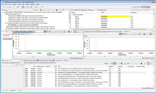
Then highlighting Non Debuggable Devices - I select "Tools/Hardware Trace Analyzer/Custom System Trace"
Cores=CSSTM_0, Transport Type=560 V2 Trace
Receiver/Transport Settings [Buffer Type (fails w/ Stop-on-full, or Circular), Buffer Size (1 MB) Number of Pins (fails w/ 4, 2, or 1), Synch trace w/ target run/halt (fails w/ on/off)]
Pressing start results in the following popup dialog box sequence...
-Progress Information - 560 V2 Trace - Calibration in progress
-X Could not run analyzer. Cause: Uninitialized error text
Launching the Target Configuration using CCS v8.3.1
I can connect connect to all 32 cores (multiple at a time) and perform source level debugging
I can then "Show all cores" followed by "connect" to all Non Debuggable Devices
Then highlighting Non Debuggable Devices - the "Tools/Hardware Trace Analyzer" menu is unpopulated
popup appears...
Initialize
Need to initialize Hardware Trace Analyzer. Proceed?
Once initialized please select the feature again from the menu to select a use case.
Initializing Use Cases...
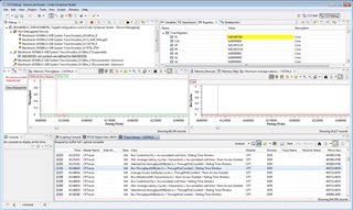
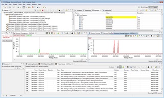
Then highlighting Non Debuggable Devices - I select "Tools/Hardware Trace Analyzer/Custom System Trace"
Cores=CSSTM_0, Transport Type=560 V2 Trace
Receiver/Transport Settings [Buffer Type (fails w/ Stop-on-full, or Circular), Buffer Size (1 MB) Number of Pins (fails w/ 4, 2, or 1), Synch trace w/ target run/halt (fails w/ on/off)]
Pressing start results in the following popup dialog box sequence...
“Progress Information – 560 V2 Trace – Calibration in progress”
“X – Could not run analyzer. Cause: failed to calibrate channel : transmitter frequency measured at 0 Hz”
The following output in Console Window…
IcePick_D: Error: (Error -2172 @ 0x0) Unable to communicate with the debug probe. Confirm debug probe configuration and connections, reset the debug probe, and retry the operation. (Emulation package 8.1.0.00012)
CS_DAP_DebugSS: Error: (Error -2172 @ 0x0) Unable to communicate with the debug probe. Confirm debug probe configuration and connections, reset the debug probe, and retry the operation. (Emulation package 8.1.0.00012)
IcePick_E: Error: (Error -2172 @ 0x0) Unable to communicate with the debug probe. Confirm debug probe configuration and connections, reset the debug probe, and retry the operation. (Emulation package 8.1.0.00012)
CS_DAP_DebugSS_0: Error: (Error -2172 @ 0x0) Unable to communicate with the debug probe. Confirm debug probe configuration and connections, reset the debug probe, and retry the operation. (Emulation package 8.1.0.00012)
IcePick_F: Error: (Error -2172 @ 0x0) Unable to communicate with the debug probe. Confirm debug probe configuration and connections, reset the debug probe, and retry the operation. (Emulation package 8.1.0.00012)
CS_DAP_DebugSS_1: Error: (Error -2172 @ 0x0) Unable to communicate with the debug probe. Confirm debug probe configuration and connections, reset the debug probe, and retry the operation. (Emulation package 8.1.0.00012)
IcePick_G: Error: (Error -2172 @ 0x0) Unable to communicate with the debug probe. Confirm debug probe configuration and connections, reset the debug probe, and retry the operation. (Emulation package 8.1.0.00012)
CS_DAP_DebugSS_2: Error: (Error -2172 @ 0x0) Unable to communicate with the debug probe. Confirm debug probe configuration and connections, reset the debug probe, and retry the operation. (Emulation package 8.1.0.00012)
IcePick_D: Unable to determine target status after 20 attempts
CS_DAP_DebugSS: Unable to determine target status after 20 attempts
IcePick_E: Unable to determine target status after 20 attempts
CS_DAP_DebugSS_0: Unable to determine target status after 20 attempts
IcePick_F: Unable to determine target status after 20 attempts
CS_DAP_DebugSS_1: Unable to determine target status after 20 attempts
IcePick_G: Unable to determine target status after 20 attempts
CS_DAP_DebugSS_2: Unable to determine target status after 20 attempts
IcePick_D: Failed to remove the debug state from the target before disconnecting.  There may still be breakpoint op-codes embedded in program memory.  It is recommended that you reset the emulator before you connect and reload your program before you continue debugging
CS_DAP_DebugSS: Failed to remove the debug state from the target before disconnecting.  There may still be breakpoint op-codes embedded in program memory.  It is recommended that you reset the emulator before you connect and reload your program before you continue debugging
IcePick_E: Failed to remove the debug state from the target before disconnecting.  There may still be breakpoint op-codes embedded in program memory.  It is recommended that you reset the emulator before you connect and reload your program before you continue debugging
CS_DAP_DebugSS_0: Failed to remove the debug state from the target before disconnecting.  There may still be breakpoint op-codes embedded in program memory.  It is recommended that you reset the emulator before you connect and reload your program before you continue debugging
IcePick_F: Failed to remove the debug state from the target before disconnecting.  There may still be breakpoint op-codes embedded in program memory.  It is recommended that you reset the emulator before you connect and reload your program before you continue debugging
CS_DAP_DebugSS_1: Failed to remove the debug state from the target before disconnecting.  There may still be breakpoint op-codes embedded in program memory.  It is recommended that you reset the emulator before you connect and reload your program before you continue debugging
IcePick_G: Failed to remove the debug state from the target before disconnecting.  There may still be breakpoint op-codes embedded in program memory.  It is recommended that you reset the emulator before you connect and reload your program before you continue debugging
CS_DAP_DebugSS_2: Failed to remove the debug state from the target before disconnecting.  There may still be breakpoint op-codes embedded in program memory.  It is recommended that you reset the emulator before you connect and reload your program before you continue debugging
TETB_STM: Error: (Error -2172 @ 0x0) Unable to communicate with the debug probe. Confirm debug probe configuration and connections, reset the debug probe, and retry the operation. (Emulation package 8.1.0.00012)
CSSTM_1: Error: (Error -2172 @ 0x0) Unable to communicate with the debug probe. Confirm debug probe configuration and connections, reset the debug probe, and retry the operation. (Emulation package 8.1.0.00012)
TETB_STM_0: Error: (Error -2172 @ 0x0) Unable to communicate with the debug probe. Confirm debug probe configuration and connections, reset the debug probe, and retry the operation. (Emulation package 8.1.0.00012)
CSSTM_2: Error: (Error -2172 @ 0x0) Unable to communicate with the debug probe. Confirm debug probe configuration and connections, reset the debug probe, and retry the operation. (Emulation package 8.1.0.00012)
TETB_STM_1: Error: (Error -2172 @ 0x0) Unable to communicate with the debug probe. Confirm debug probe configuration and connections, reset the debug probe, and retry the operation. (Emulation package 8.1.0.00012)
TETB_STM_2: Error: (Error -2172 @ 0x0) Unable to communicate with the debug probe. Confirm debug probe configuration and connections, reset the debug probe, and retry the operation. (Emulation package 8.1.0.00012)
TETB_STM: Unable to determine target status after 20 attempts
CSSTM_1: Unable to determine target status after 20 attempts
TETB_STM_0: Unable to determine target status after 20 attempts
CSSTM_2: Unable to determine target status after 20 attempts
TETB_STM_1: Unable to determine target status after 20 attempts
TETB_STM_2: Unable to determine target status after 20 attempts
TETB_STM: Failed to remove the debug state from the target before disconnecting.  There may still be breakpoint op-codes embedded in program memory.  It is recommended that you reset the emulator before you connect and reload your program before you continue debugging
CSSTM_1: Failed to remove the debug state from the target before disconnecting.  There may still be breakpoint op-codes embedded in program memory.  It is recommended that you reset the emulator before you connect and reload your program before you continue debugging
TETB_STM_0: Failed to remove the debug state from the target before disconnecting.  There may still be breakpoint op-codes embedded in program memory.  It is recommended that you reset the emulator before you connect and reload your program before you continue debugging
CSSTM_2: Failed to remove the debug state from the target before disconnecting.  There may still be breakpoint op-codes embedded in program memory.  It is recommended that you reset the emulator before you connect and reload your program before you continue debugging
TETB_STM_1: Failed to remove the debug state from the target before disconnecting.  There may still be breakpoint op-codes embedded in program memory.  It is recommended that you reset the emulator before you connect and reload your program before you continue debugging
TETB_STM_2: Failed to remove the debug state from the target before disconnecting.  There may still be breakpoint op-codes embedded in program memory.  It is recommended that you reset the emulator before you connect and reload your program before you continue debugging
CSSTM_3: Error: (Error -2172 @ 0x0) Unable to communicate with the debug probe. Confirm debug probe configuration and connections, reset the debug probe, and retry the operation. (Emulation package 8.1.0.00012)
CSSTM_3: Unable to determine target status after 20 attempts
CSSTM_3: Failed to remove the debug state from the target before disconnecting.  There may still be breakpoint op-codes embedded in program memory.  It is recommended that you reset the emulator before you connect and reload your program before you continue debugging
CSSTM_0: Error: (Error -2172 @ 0x0) Unable to communicate with the debug probe. Confirm debug probe configuration and connections, reset the debug probe, and retry the operation. (Emulation package 8.1.0.00012)
CSSTM_0: Unable to determine target status after 20 attempts
CSSTM_0: Failed to remove the debug state from the target before disconnecting.  There may still be breakpoint op-codes embedded in program memory.  It is recommended that you reset the emulator before you connect and reload your program before you continue debugging
Any ideas or insights into what's preventing System Trace from working would be greatly appreciated
Thanks!
George