This thread has been locked.

If you have a related question, please click the "Ask a related question" button in the top right corner. The newly created question will be automatically linked to this question.

SK-AM62: USB's Test Mode Verification

Part Number: SK-AM62

Tool/software:

From SPRUIV7B – MAY 2022 technical reference manual, I'm able to set the test mode control under TSTCTL[4:1] of VBP2AHB_CONTROLLER_VBP_USB3_CORE_DEV_DCTL Register. For the 4'b100:
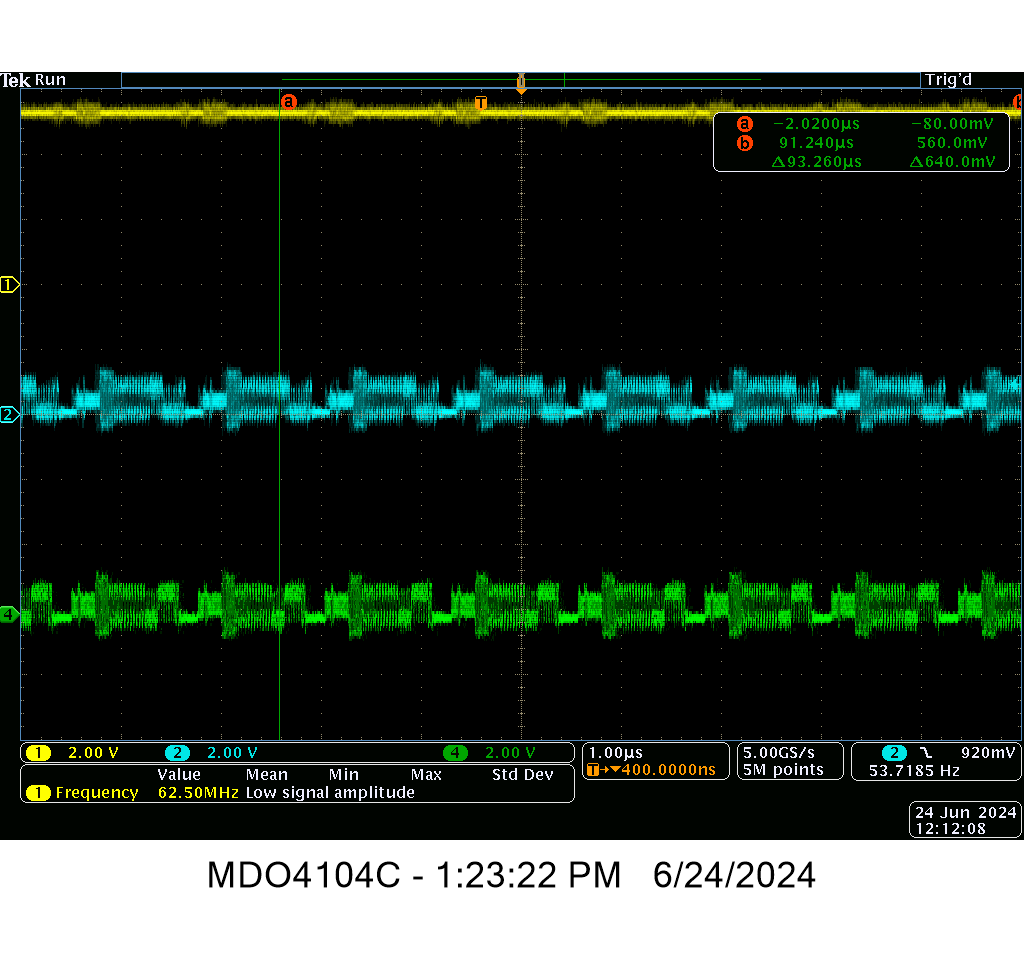
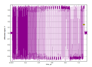
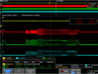
Test_Packet mode, is there any reference diagram/picture of repeated output signal to make sure the signal is correct?

  • Hello CWL, 

    Thank you for the query.

    I am not aware of any document that provides the information you are looking for.

    Did you try looking at the USB standards ?

    Regards,

    Sreenivasa

  • Hi Sreenivasa,

    From usb specifications, chapter 7.1.20 Test Mode Support. It have a table of repeated data for test pattern. But currently I don't have any equipment to verify the data, so what I hope is just verify the data pattern by using an oscilloscope. 

    From sharing of HW colleague, the data should be something like eye jitter diagram in another processor. But currently from what I got in Sitara SK-AM62, it doesn't looks something like that. Thus, I'm checking is there any documents to verify this.

    I'm also check do I need to update the USB0_PHY_CTRL_PLL_REF_SEL[3:0] of CFG0_USB0_PHY_CTRL Registers to make sure the test pattern is correct. Or do we have any documents for how to correctly setup the test pattern? 

    Thanks.

  • Hello CWL, 

    Can you run the below commands and let me know if this helps.

    I will assign to our USB expert based on your inputs.

    Please run the below tests and let me know if the below commands work.

    1. Enter TEST_PACKET compliance mode by entering the below test commands:

     USB0

    >> devmem2 0x31000420 w 0xA0

    >> devmem2 0x31000020 w 0x4

    >> devmem2 0x31000424 w 0x40000000

               USB1

    >> devmem2 0x31100420 w 0xA0

    >> devmem2 0x31100020 w 0x4

    >> devmem2 0x31100424 w 0x40000000

    Regards,

    Sreenivasa

  • Hi Sreenivasa,

    In the SK-AM62 evk, after power up the LPSC_USB_1, LPSC_MAIN_USB1_ISO, the recommended xHCI registers are having the following value.
    0x31100420 -> 0x00000280
    0x31100020 -> 0x00000000
    0x31100424 -> 0x00000000

    And after I did the suggested write to USB1. I don't see any signal changes in the 5V, D+ and D-. 

    USB1

    >> devmem2 0x31100420 w 0xA0

    >> devmem2 0x31100020 w 0x4

    >> devmem2 0x31100424 w 0x40000000

    My questions now is do we want to make sure the USB enter certain link state before make sure it enter test mode, eg like Powered-off state (as showed in Intel xHCI manual chapter 4.19.1.1.

  • The following is the register value after written the suggested value:
    0x31100420 -> 0x00000080

    0x31100020 -> 0x00000004

    0x31100424 -> 0x40000000

    After some reading of the 0x31100420 add, the value is still not remain in one state.

    The example as below:

    0x31100420 -> 0x00000C80

    0x31100420 -> 0x00000080

    0x31100420 -> 0x00000C80

    0x31100420 -> 0x00000160

    0x31100420 -> 0x00000080

  • Hello CWL, 

    Let me check and assign the thread to an expert.

    Regards,

    Sreenivasa

  • Hi Screenivasa,

    Thanks. As reminder, I can see some test packet after setting of TSTCTL[4:1] of VBP2AHB_CONTROLLER_VBP_USB3_CORE_DEV_DCTL Register with VBUS is on. But I'm just looking a way to verify the test packet.

    Thanks.

  • Hello CWL, 

    Thank you.

    I need you to elaborate the above note.

    I assume you are able to enter the test mode and generate the required waveform, Is that correct,

    But I'm just looking a way to verify the test packet.

    Help me understand what you mean by verify.

    Regards,

    Sreenivasa

  • Hi Screenivasa,

    After setting of TSTCTL[4:1], I saw there are some data or signal is sending in USB's D+, D- signal. By verify mean how I know is the data send out is correct. 

  • Hello CWL, 

    Thank you.

    I suspect you want to know if the data sent out is correct by using a scope or USB protocol analyzer. Help me understand your use case.

    Are you able to share the waveform you are observing for me to check with the experts.

    Regards,

    Sreenivasa


  • I'm checking by using an oscilloscope. Currently I'm having data like this.

  • By reference other processor than TI, I got some data like this in D+, D- line.
    This signal is what I expected in other processor than TI.

  • These signal are from usb2.0 port.

  • Hello CWL,

    Thank you.

    Let me check with the expert.

    Regards,

    Sreenivasa

  • Hi CWL,

    In the SK-AM62 evk, after power up the LPSC_USB_1, LPSC_MAIN_USB1_ISO, the recommended xHCI registers are having the following value.
    0x31100420 -> 0x00000280
    0x31100020 -> 0x00000000
    0x31100424 -> 0x00000000

    Do you run Processor SDK Linux on your SK-AM62 board? With the SDK default Linux SD card Image, you don't need specifically to do anything on the USB1 interface, is it already in host mode, and you only need to run the 3 devmem2 commands which Sreenivasa provided above to let USB1 to send out the USB test packets.

  • Hi CWL,

    Can you help to share the test waveform when using a differential probe? It should look something like this.

    Best regards,

    Luis Parga

  • Hi Bin Liu,

    Previously, I doesn't run Processor SDK Linux. I'm just using our developed software to alternate the value of register.
    Today, I had tried to do that with a SD card boot (image: tisdk-default-image-am62xx-evm.wic). I got the signal generated after follow the "devmem" steps as pictures below.


    So now, I have to figure out how can I achieve this without using the processor SDK linux in our software.

  • Hello CWL, 

    Thank you for updating the progress.

    Regards,

    Sreenivasa