This thread has been locked.

If you have a related question, please click the "Ask a related question" button in the top right corner. The newly created question will be automatically linked to this question.

PROCESSOR-SDK-AM64X: GPIO Interrupt Configuration

Part Number: PROCESSOR-SDK-AM64X
Other Parts Discussed in Thread: SYSCONFIG

Tool/software:

Hello,

I have a question regarding the GPIO interrupt configuration procedure on the AM243x.

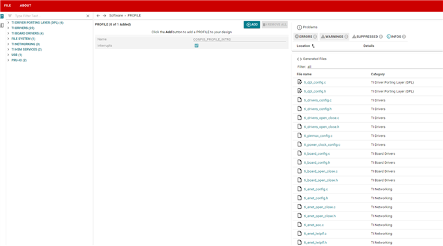
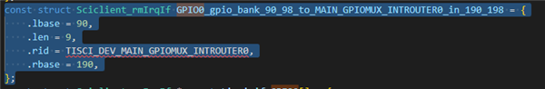
Below is the SciClient message that gets generate to enable the interrupt on a given GPIO based on the files generated from the SysConfig tool

However, the function asserts when I run this on our chip.

After some investigation, I found that there are different values for the interrupt routers that can be used based on which GPIO is being configured.

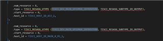
There's these ones in the cslr_intr_r5fss0_core0.h

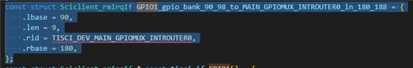
And then theres an interrupt router defined for each GPIOs in the cslr_intr_main_gpiomux_introuter0.h

as well as routers specifically for each GPIO bank


Which one should I use?

Thanks!

Eden

  • Hello Eden,

    Which one should I use?

    Please refer to the section 9.3.2 INTRTR Integration of TRM for more information on GPIO Routers.

    Please see below screenshot.

    Can you please also specify what is your use case and which GPIO pin you want to control?

    Regards,

    Tushar

  • There are 2 pins I'm trying to configure as GPIO interrupts.

    GPIO1_5 (MAIN domain, GPIO instance 1, pin number 5 which is in bank 0)
    GPIO1_55 (MAIN domain, GPIO instance 1, pin number 55 which is in bank 3)

    They are both configured as inputs.

    Another thing. In your API, there is this following example on how to use the SciClient to configure the interrupt route

    As you can see from the highlights text, some modifications need to be done to the sciclient_defaultBoardCfg_rm.c file. However, after taking a look at that file I don't see any explanation (or any example from your API or documents) on how to modify it for my needs.

  • Hello Eden,

    There are 2 pins I'm trying to configure as GPIO interrupts.

    You can refer to the existing GPIO input interrupt example provided in MCU+SDK for interrupt configuration. Please refer DRIVERS_GPIO to know more about GPIO configuration.

    As you can see from the highlights text, some modifications need to be done to the sciclient_defaultBoardCfg_rm.c file. However, after taking a look at that file I don't see any explanation (or any example from your API or documents) on how to modify it for my needs.

    The sciclient_defaultBoardCfg_rm.c file contains information about resources allocated among various host. To know more on how to allocate resources, please refer RESOURCE_ALLOCATION.

    Regards,

    Tushar

  • I checked out the RESOURCE_ALLOCATION in the API docs that you posted. In the example, it shows that you can do it with the sysconfig tool. However, the example seems to be displaying options in the sysconfig tool that I don't have in mine. Here's what mine looks like

    As you can see on the left hand side tab, the options that I have do not include the SYSFW RESOURCE PARTITION option like in the example you supplied.

  • Hello Eden,

    Thank you for your response.

    the example seems to be displaying options in the sysconfig tool that I don't have in mine

    The above screenshot is showing the basic Pinmux features of sysconfig tool coming from MCU+SDK.

    Have you tried running the below command from root directory of MCU+SDK?

    gmake -s -C tools/sysfw/boardcfg configure SOC=am64x

    Please follow the steps suggested here to change the default resource allocation. 

    Please let us know if you face any difficulty.

    Regards,

    Tushar

  • I'm getting the following error when I run the command:


  • Hello Eden,

    Can you please confirm, do you have sysconfig v1.18 installed at your system?

    The above error is coming because you do not have sysconfig v1.18 installed at C:\ti location.

    Regards,

    Tushar

  • Ok I managed to make the tool work with an updated version of the sdk.

    However I still have difficulty understanding the connection between the interrupt route and the ressources that are currently allocated on my board.

    Firstly, I don't understand the concept of "islands"


    From the image below we see that TISCI_HOST_ID_MAIN_0 and TISCI_HOST_ID_MAIN_1 each have 4 "islands" (index o to 3). If I'm only using the R5FSS0_CORE0, what "islands" should I be using and/or allocating?

    Second, I'm trying to trigger interrupts on GPIO1_5 and GPIO1_55 which are in the MAIN domain. If I refer to the diagrams you posted above, there are different routes I can use. They are shown below in highlighted text.

    But based on all the possible sources I can use for my SciClient message I don't really know which ones I should use. There is also CSLR_MAIN_GPIOMUX_INTEROUTER0_IN_GPIO[0:1]_GPIO_[0:89] I can use as well as CSLR_MAIN_GPIOMUX_INTEROUTER0_IN_GPIO[0:1]_BANK_[0:8].

    For context, in my ressource partitioning, there are 2 available Main GPIO Interrupt Router Count ressources in each of MAIN_0_R5_1, MAIN_0_R5_3, MAIN_1_R5_1 and MAIN_0_R5_3 partitions.

  • Also, when I try to generate the new files after modifying the resource partitions, I get the following error

  • Hello Eden,

    Can you please confirm, Do you have CCS v12.7 installed in your system?

    The above error is coming because you might not have CCS v12.7 installed at your system.

    The CCS v12.7 should be installed at location C:\ti.

    Regards,

    Tushar

  • Hello Eden,

    Firstly, I don't understand the concept of "islands"

    The island is nothing but a name given to particular region. The MAIN island here refers to the MAIN domain.

    Please refer to the Introduction section of TRM to know more about Device Overview, MAIN & MCU Domain.

    From the image below we see that TISCI_HOST_ID_MAIN_0 and TISCI_HOST_ID_MAIN_1 each have 4 "islands" (index o to 3). If I'm only using the R5FSS0_CORE0, what "islands" should I be using and/or allocating?

    Please refer to the TISCI documentation to know more about what each Host ID means. Please refer AM64x_HOST.

    From the image below we see that TISCI_HOST_ID_MAIN_0 and TISCI_HOST_ID_MAIN_1 each have 4 "islands" (index o to 3). If I'm only using the R5FSS0_CORE0, what "islands" should I be using and/or allocating?

    You should use the TISCI_HOST_ID_MAIN_0_R5_1 for R5FSS0_CORE0.

    If I refer to the diagrams you posted above, there are different routes I can use. They are shown below in highlighted text.

    In the above image there is only one interrupt router which is GPIOMUX_INTRTR0. You need to configure this router only and specify the core on which the interrupt should be routed. The sysconfig tool will generate the appropriate code as configured. Please refer GPIO_INPUT_INTERRUPT for reference.

    There is also CSLR_MAIN_GPIOMUX_INTEROUTER0_IN_GPIO[0:1]_GPIO_[0:89] I can use as well as CSLR_MAIN_GPIOMUX_INTEROUTER0_IN_GPIO[0:1]_BANK_[0:8].

    This are the interrupt inputs signals to the GPIOMUX_INTRTR0.

    Hope the above information helps.

    Regards,

    Tushar

  • I installed ccs v12.7 and the configure-gen still doesn't work

  • Hello Eden,

    Can you please share the path of CCS root directory?

    Have you installed CCS v12.7.1 or 12.7.0? The gmake tool is looking for CCS root directory at path C:\ti\ccs1270.

    Please check in your system does the C:\ti\ccs1270 exists or not?

    Regards,

    Tushar

  • I installed 1271 you're right. I will try with 1270. The tool will then be able to find the ti\ccs1271 path.

    Now for the interrupts. I managed to successfully send an sci client message to route one of my two gpio interrupts. The second one still fails.

    Here is what I did:

    First, in the example given by TI and in your API docs, it seems like the rmIrqReq.src_index parameter is wrong. Below is the generated example from the sysconfig tool

    As you can see from the line denoted by the red arrow, the src index is

    TISCI_BANK_SRC_IDX_BASE_GPIO1 + GPIO_GET_BANK_INDEX(43)

    Here, I'm assuming you are routing the interrupt line with the ID of the bank of the GPIO.

    The TISCI_BANK_SRC_IDX_BASE_GPIO1 value is 90U.

    The GPIO_GET_BANK_INDEX(43) returns 2 (as GPIO1_43 is in bank number 2 of GPIO1).

    Therefore, the scr index is set to 90 + 2 which is 92.

    HOWEVER, in the cslr_intr_main_gpiomux_interouter0.h file (which lists the interrupt sources for the MAIN_GPIOMUX_INTEROUTER0 receiver), the source interrupt ID (src index) for a pin on bank2 of GPIO1 is 182U. This can be seen here

    #define CSLR_MAIN_GPIOMUX_INTROUTER0_IN_GPIO1_GPIO_BANK_2              (182U)

    There is a 90U offset in this case.

    If you look at cslr_intr_main_gpiomux_interouter0.h file, you will see that you can select the src index for routing the GPIO interrupts either by individual pins, or by the banks they are located in.

    Pins 0 to 89 of GPIO instance 0 (GPIO0_0 -> GPIO0_89) have values 0U to 89U.

    Pins 0 to 89 of GPIO instance 1 (GPIO1_0 -> GPIO1_89) have values of 90U to 179U.

    Then, if you want to route the interrupt from the source of a bank of GPIOs, you have the following:

    Banks 0 to 8 of GPIO instance 1 (GPIO1_GPIO_BANK_0 -> GPIO1_GPIO_BANK_8) have values 180U to 188U.

    Banks 0 to 8 of GPIO instance 0 (GPIO0_GPIO_BANK_0 -> GPIO0_GPIO_BANK_8) have values of 190U to 198U.

    Using this information, if I want to trigger an interrupt on pin 7 of GPIO instance 1 (GPIO1_7), that would correspond to a src_index of 97U (90U + 7U). Using that source index with a destination host irq CSLR_RF5SS0_COR0_INTR_MAIN_GPIOMUX_INTEROUTER_OUTP_0 will send an sciclient message of IRQSET that won't assert on an error.

    Using the same logic to trigger an additional interrupt on pin 55 of GPIO instance 1 (GPIO1_55), it would correspond to a src_index of 145U (90U + 55U). However, I tried every possible destination host irq (CSLR_RF5SS0_COR0_INTR_MAIN_GPIOMUX_INTEROUTER_OUTP_0-15) and the sciclient message will assert on an error which seems to say that it can't validate the route.

    Is there something specific I need to do if I want to route 2 different GPIO interrupts but that are on different GPIO banks?

  • Hello Eden,

    Please find the description of above mentioned parameters.

    rmIrqReq.src_id = TISCI_DEV_GPIO1 configures the GPIO1 module as source.

    rmIrqReq.src_index = TISCI_BANK_SRC_IDX_BASE_GPIO1 + GPIO_GET_BANK_INDEX(43) configures the GPIO1 module as Bank Interrupt.

    rmIrqReq.dst_id = TISCI_DEV_R5FSS0_CORE0 configures R5FSS0-0 as the destination core.

    mIrqReq.dst_host_irq = CSLR_RF5SS0_COR0_INTR_MAIN_GPIOMUX_INTEROUTER_OUTP_7 configures the router number 7 to be used which corresponds to interrupt number 39.

    Is there something specific I need to do if I want to route 2 different GPIO interrupts but that are on different GPIO banks?

    You will need to enable bank interrupts for both GPIO banks using GPIO_bankIntrEnable() API.

    Please refer GPIO_API.

    Your sysconfig generated function should look like the below provided code.(i.e. configured GPIO1_7 and GPIO1_55 pin to router 7 and 6 respectively).

    static void Sciclient_gpioIrqSet(void)
    {
        int32_t                             retVal;
        struct tisci_msg_rm_irq_set_req     rmIrqReq;
        struct tisci_msg_rm_irq_set_resp    rmIrqResp;
        rmIrqReq.valid_params           = 0U;
        rmIrqReq.valid_params          |= TISCI_MSG_VALUE_RM_DST_ID_VALID;
        rmIrqReq.valid_params          |= TISCI_MSG_VALUE_RM_DST_HOST_IRQ_VALID;
        rmIrqReq.global_event           = 0U;
        rmIrqReq.src_id                 = TISCI_DEV_GPIO1;
        rmIrqReq.src_index              = TISCI_BANK_SRC_IDX_BASE_GPIO1 + GPIO_GET_BANK_INDEX(7);
        rmIrqReq.dst_id                 = TISCI_DEV_R5FSS0_CORE0;
        rmIrqReq.dst_host_irq           = CSLR_R5FSS0_CORE0_INTR_MAIN_GPIOMUX_INTROUTER0_OUTP_7;
        rmIrqReq.ia_id                  = 0U;
        rmIrqReq.vint                   = 0U;
        rmIrqReq.vint_status_bit_index  = 0U;
        rmIrqReq.secondary_host         = TISCI_MSG_VALUE_RM_UNUSED_SECONDARY_HOST;
    
        retVal = Sciclient_rmIrqSet(&rmIrqReq, &rmIrqResp, SystemP_WAIT_FOREVER);
        if(0 != retVal)
        {
            DebugP_log("[Error] Sciclient event config failed!!!\r\n");
            DebugP_assert(FALSE);
        }
        rmIrqReq.valid_params           = 0U;
        rmIrqReq.valid_params          |= TISCI_MSG_VALUE_RM_DST_ID_VALID;
        rmIrqReq.valid_params          |= TISCI_MSG_VALUE_RM_DST_HOST_IRQ_VALID;
        rmIrqReq.global_event           = 0U;
        rmIrqReq.src_id                 = TISCI_DEV_GPIO1;
        rmIrqReq.src_index              = TISCI_BANK_SRC_IDX_BASE_GPIO1 + GPIO_GET_BANK_INDEX(55);
        rmIrqReq.dst_id                 = TISCI_DEV_R5FSS0_CORE0;
        rmIrqReq.dst_host_irq           = CSLR_R5FSS0_CORE0_INTR_MAIN_GPIOMUX_INTROUTER0_OUTP_6;
        rmIrqReq.ia_id                  = 0U;
        rmIrqReq.vint                   = 0U;
        rmIrqReq.vint_status_bit_index  = 0U;
        rmIrqReq.secondary_host         = TISCI_MSG_VALUE_RM_UNUSED_SECONDARY_HOST;
    
        retVal = Sciclient_rmIrqSet(&rmIrqReq, &rmIrqResp, SystemP_WAIT_FOREVER);
        if(0 != retVal)
        {
            DebugP_log("[Error] Sciclient event config failed!!!\r\n");
            DebugP_assert(FALSE);
        }
        return;
    }

    Regards, 

    Tushar

  • Ok that seemed to work for both my interrupts. Thanks!

    However, I have a couple questions.

    When you set

    rmIrqReq.src_index = TISCI_BANK_SRC_IDX_BASE_GPIO1 + GPIO_GET_BANK_INDEX(7)

    that value is 90 (90 + 0) where the offset is 90 and the bank index is 0 because GPIO1_7 is in bank 0. But when you look at all the source interrupt Ids in the cslr_intr_main_gpiomux_interouter0.h header file, the value 90U is assigned to, if I understand correctly, GPIO1_0 pin interrupt (not bank interrupt). You can see this with the following image

    If I'm setting it through a bank interrupt (in the case of GPIO1_7 it would be GPIO1_BANK0), shouldn't the value be 180U like so

    Also, how did you know that I should use

    CSLR_RF5SS0_COR0_INTR_MAIN_GPIOMUX_INTEROUTER_OUTP_7 

    and

    CSLR_RF5SS0_COR0_INTR_MAIN_GPIOMUX_INTEROUTER_OUTP_6

    respecitvely? From my resource allocation file I can sort of deduce that for r5f0_core0 I can use the outputs 0 to 8 as there are 8 resources available at index 0.

    Thanks!

  • Hello Eden,

    Ok that seemed to work for both my interrupts. Thanks!

    Thanks for your confirmation.

    If I'm setting it through a bank interrupt (in the case of GPIO1_7 it would be GPIO1_BANK0), shouldn't the value be 180U like so

    This values are automatically propagated according to the rmIrqReq.src_id passed in the Sciclient_gpioIrqSet fucntion. This values are referenced from the sciclient_irq_rm.c file located at ${MCU+SDK}\source\drivers\sciclient\soc\am64x_am243x path.

    Please refer to below screenshots

    Also, how did you know that I should use

    CSLR_RF5SS0_COR0_INTR_MAIN_GPIOMUX_INTEROUTER_OUTP_7 

    and

    CSLR_RF5SS0_COR0_INTR_MAIN_GPIOMUX_INTEROUTER_OUTP_6

    respecitvely?

    Please refer to the sciclient_defaultBoardcfg_rm.c file located at ${MCU+SDK}\source\drivers\sciclient\sciclient_default_boardcfg\am64x directory to see all the resource allocation. The GPIOMUX Router number 0 to 7 are allocated/shared between R5FSS & A53SS core.  

    Please refer below screenshot.

    Hope the above information helps.

    Regards,

    Tushar