This thread has been locked.

If you have a related question, please click the "Ask a related question" button in the top right corner. The newly created question will be automatically linked to this question.

TDA4VL-Q1: J721S2 GPIO interrupt callback

Part Number: TDA4VL-Q1

Tool/software:

Hi Expers.

I'm trying to use WKUP_GPIO0_34 pin on MCU2_0 for interrupt callback.

I start from the PDK gpio led_blank sample.

Adding GPIO_CFG_IN_INT_BOTH_EDGES flag in gpioPinConfigs[].

The GPIO_Read(0) can return the high/low level change and GPIO_enableInt(0) is called,

but my callback function is executed.

Is there any sample code and document that I can reference?

  • Hi,

    Can you clarify what the issue is?

    There is an interrupt and callback called when your read a GPIO pin?
    Thanks,
    Neehar

  • My main goal is to make the interrupt working at falling edge.

  • Hi,

    Were you able to run the GPIO Led Blink example?

    Instead of manipulating gpioPinConfigs[] with GPIO_CFG_IN_INT_BOTH_EDGES, use GPIO_CFG_IN_INT_FALLING instead to configure interrupt only on falling edge of clock.

    Thanks,

    Neehar

  • yes, i can run LedBlank example. the GPIO is blanking, but the AppGpioCallbackFxn() was not been triggered.

  • Hi,

    If the callback function is not triggered, then the test is not passing correct? And the blink iterations are not printed on the UART console?

    Are you running the example on a custom board or TI EVM?

    Thanks,

    Neehar

  • I am running on our custom board. The test was not stopped, Uart console keep printing "Blink Iteration - 0 / 0".

  • Im sorry. the "Blink Iteration - 0 / 0" is my modification. the 0 / 0 represent "gpio_intr_triggered" and "last_gpio_intr_count"

  • Hi,

    Have you made any other modifications? If "gpio_intr_triggered" and "last_gpio_intr_count" are equal, the test should not pass and the blink iterations should not be printed on the UART console.
    Thanks,

    Neehar

  • The test did not pass. It stock in a infinite loop.

    and I change GPIO_board.h:

    213: #define GPIO_LED0_PIN_NUM        34 /*BOARD_USER_LED1*/ /* Pin 6 */

  • Hi,

    Can you check the INTSTAT register to see if the interrupt is triggered?

    Thanks,

    Neehar

  • Which register should I looking at?

    I print out all GPIO_INTSTAT registers.

    UART_printf("\n Blink Iteration - %d / %d\n", gpio_intr_triggered,last_gpio_intr_count);
    UART_printf("INTSTAT34 %X\n", HW_RD_REG32( 0x42110034U ));
    UART_printf("INTSTAT5C %X\n", HW_RD_REG32( 0x4211005CU ));
    UART_printf("INTSTAT84 %X\n", HW_RD_REG32( 0x42110084U ));
    UART_printf("INTSTATAC %X\n", HW_RD_REG32( 0x421100ACU ));
    UART_printf("INTSTATD4 %X\n", HW_RD_REG32( 0x421100D4U ));

    this is the output:
    Blink Iteration - 0 / 0

    INTSTAT34 0

    INTSTAT5C 4

    INTSTAT84 0

    INTSTATAC 0

    INTSTATD4 0

  • Hi,
    Each INTSTAT register will incorporate the interrupt status for two banks. Since you are using pin 34, it will be bank 3 bit 3 which is set to one showing the interrupt has occurred for that bank.

    Can you also confirm that SET_FAL_TRIG register bit is set as you want interrupt for falling edge?
    Thanks,

    Neehar

  • Hello, similarly this sample doesn't work for me on the EVM board as it is in the SDK. The pad being configured is has GPIO0_5, not 11. There is also no PADCONFIG for the WKUP_PIN. However, when I disable the WKUP_PIN calls and changed the pin number from 11 to 50,  I still wait on the callback with no change.

  • Hi Ozan,

    Can you create a separate thread for this issue? We will be able to assist you there.
    Thanks,

    Neehar

  • UART_printf("SET_FAL2C %X\n", HW_RD_REG32( 0x4211002CU ));
    UART_printf("SET_FAL54 %X\n", HW_RD_REG32( 0x42110054U ));
    UART_printf("SET_FAL7C %X\n", HW_RD_REG32( 0x4211007CU ));
    UART_printf("SET_FALA4 %X\n", HW_RD_REG32( 0x421100A4U ));
    UART_printf("SET_FALCC %X\n", HW_RD_REG32( 0x421100CCU ));

    SET_FAL2C 0

    SET_FAL54 0

    SET_FAL7C 0

    SET_FALA4 0

    SET_FALCC 0

  • Hi,

    Instead of manipulating gpioPinConfigs[] with GPIO_CFG_IN_INT_BOTH_EDGES, use GPIO_CFG_IN_INT_FALLING instead to configure interrupt only on falling edge of clock.

    Do the SET_FAL_TRIG  register values include these changes made to the gpioPinConfigs[]?

    Thanks,

    Neehar

  • I had set gpioPinConfigs[] to GPIO_CFG_IN_INT_FALLING.

    I write 0xFF to INTSTAT5C(0x4211005C). The INTSTAT5C can be clear, and trigger again.

  • Hi,

    Thanks for this information.

    Can you confirm which core you are building the example for?
    Thanks,

    Neehar

  • I am using mcu2_0.

    make GPIO_LedBlink_TestApp_freertos  BOARD=j721s2_evm CORE=mcu2_0

    SDK and PDK version. ti-processor-sdk-rtos-j721s2-evm-08_06_01_03/pdk_j721s2_08_06_01_03

  • Hi,

    Can you provide the output console logs and INTSTAT registers if you revert the changes made to GPIO_board.h? As in using the original GPIO_board.h file even if the physical LED will not blink.
    Thanks,

    Neehar

  • Hi,

    I just notice that the trigger type was set to GPIO_CFG_IN_INT_RISING.

    set to GPIO_CFG_IN_INT_FALLING, the SET_FAL value was 4.

    this is the uart log.

    **********************************************************
    Termite log, started at Thu Aug  1 09:31:09 2024
    **********************************************************
    
    
    IntConfig:  portNum[0], pinNum[34], bankNum[2], intNum[0], eventId[0]
    
     GPIO Led Blink Application 


     Awaiting interrupt occurrence 


     Blink Iteration - 0 / 0
    
    INTSTAT34 0
    
    INTSTAT5C 0
    
    INTSTAT84 0
    
    INTSTATAC 0
    
    INTSTATD4 0
    
    SET_FAL2C 0
    
    SET_FAL54 4
    
    SET_FAL7C 0
    
    SET_FALA4 0
    
    SET_FALCC 0
    
    INTSTAT5C 0 after WR1


     Blink Iteration - 0 / 0
    
    INTSTAT34 0
    
    INTSTAT5C 4
    
    INTSTAT84 0
    
    INTSTATAC 0
    
    INTSTATD4 0
    
    SET_FAL2C 0
    
    SET_FAL54 4
    
    SET_FAL7C 0
    
    SET_FALA4 0
    
    SET_FALCC 0
    
    INTSTAT5C 0 after WR1


     Blink Iteration - 0 / 0
    
    INTSTAT34 0
    
    INTSTAT5C 0
    
    INTSTAT84 0
    
    INTSTATAC 0
    
    INTSTATD4 0
    
    SET_FAL2C 0
    
    SET_FAL54 4
    
    SET_FAL7C 0
    
    SET_FALA4 0
    
    SET_FALCC 0
    
    INTSTAT5C 0 after WR1


     Blink Iteration - 0 / 0
    
    INTSTAT34 0
    
    INTSTAT5C 4
    
    INTSTAT84 0
    
    INTSTATAC 0
    
    INTSTATD4 0
    
    SET_FAL2C 0
    
    SET_FAL54 4
    
    SET_FAL7C 0
    
    SET_FALA4 0
    
    SET_FALCC 0
    
    INTSTAT5C 0 after WR1


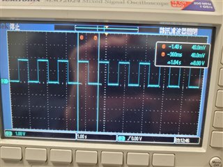
    oscilloscope on the pin.

    led_blink.tar.gz

  • Hi,

    The interrupt is getting triggered as INTSTAT23 is updated every time but the callback function is still not getting called.

    Can you revert to the original GPIO pinNum in GPIO_board.h and send the logs again?
    Thanks,

    Neehar

  • Hi, sorry for the late reply.

    I use the original GPIO_board.h. and keep the custom main_led_blink.c.

    It keep showing

    IntConfig:  portNum[0], pinNum[34], bankNum[2], intNum[0], eventId[0]

    about every 2 second.

    **********************************************************
    Termite log, started at Thu Aug 29 10:51:26 2024
    **********************************************************
    
    **********************************************************
    Termite log, started at Thu Aug 29 10:51:33 2024
    **********************************************************
    
    
    IntConfig:  portNum[0], pinNum[6], bankNum[0], intNum[0], eventId[0]
    
    IntConfig:  portNum[0], pinNum[6], bankNum[0], intNum[0], eventId[0]
    
    IntConfig:  portNum[0], pinNum[6], bankNum[0], intNum[0], eventId[0]
    
    IntConfig:  portNum[0], pinNum[6], bankNum[0], intNum[0], eventId[0]
    
    IntConfig:  portNum[0], pinNum[6], bankNum[0], intNum[0], eventId[0]�
    
    IntConfig:  portNum[0], pinNum[6], bankNum[0], intNum[0], eventId[0]
    
    IntConfig:  portNum[0], pinNum[6], bankNum[0], intNum[0], eventId[0]
    
    IntConfig:  portNum[0], pinNum[6], bankNum[0], intNum[0], eventId[0]

  • The UART0, the SBL debug maeeage, shows that it is rebooting again and again.

  • Hi,

    The UART0, the SBL debug maeeage, shows that it is rebooting again and again.

    This seems to be due to a boot issue as the logs did not show repeats before correct?
    Have you made any further changes to SBL or your application?
    Thanks,

    Neehar

  • We made some changes for our DDR in /ti/board/.

    I think I'll get our evm board and try again.

  • Hi,

    Got it, let me know what your results are.

    Thanks,

    Neehar

  • **********************************************************
    Termite log, started at Thu Sep  5 11:58:05 2024
    **********************************************************
    
    **********************************************************
    Termite log, started at Thu Sep  5 11:58:08 2024
    **********************************************************
    
    
    IntConfig:  portNum[0], pinNum[6], bankNum[0], intNum[0], eventId[0]IN ISR1 


     GPIO Led Blink Application 


     Awaiting interrupt occurrence 
    
    IN ISR2 


     Blink Iteration - 2 / 0
    
    INTSTAT34 0
    
    INTSTAT5C 0
    
    INTSTAT84 0
    
    INTSTATAC 0
    
    INTSTATD4 0
    
    SET_FAL2C 0
    
    SET_FAL54 0
    
    SET_FAL7C 0
    
    SET_FALA4 0
    
    SET_FALCC 0
    
    INTSTAT5C 0 after WR1


     Blink Iteration - 2 


     All tests have passed 
    
    IN ISR3 


     Blink Iteration - 3 / 2
    
    INTSTAT34 0
    
    INTSTAT5C 0
    
    INTSTAT84 0
    
    INTSTATAC 0
    
    INTSTATD4 0
    
    SET_FAL2C 0
    
    SET_FAL54 0
    
    SET_FAL7C 0
    
    SET_FALA4 0
    
    SET_FALCC 0
    
    INTSTAT5C 0 after WR1


     Blink Iteration - 3 


     All tests have passed 
    
    IN ISR4 


     Blink Iteration - 4 / 3
    
    INTSTAT34 0
    
    INTSTAT5C 0
    
    INTSTAT84 0
    
    INTSTATAC 0
    
    INTSTATD4 0
    
    SET_FAL2C 0
    
    SET_FAL54 0
    
    SET_FAL7C 0
    
    SET_FALA4 0
    
    SET_FALCC 0
    
    INTSTAT5C 0 after WR1


     Blink Iteration - 4 


     All tests have passed 
    
    IN ISR5 


     Blink Iteration - 5 / 4
    
    INTSTAT34 0
    
    INTSTAT5C 0
    
    INTSTAT84 0
    
    INTSTATAC 0
    
    INTSTATD4 0
    
    SET_FAL2C 0
    
    SET_FAL54 0
    
    SET_FAL7C 0
    
    SET_FALA4 0
    
    SET_FALCC 0
    
    INTSTAT5C 0 after WR1


     Blink Iteration - 5 


     All tests have passed 
    
    IN ISR6 


     Blink Iteration - 6 / 5
    
    INTSTAT34 0
    
    INTSTAT5C 0
    
    INTSTAT84 0
    
    INTSTATAC 0
    
    INTSTATD4 0
    
    SET_FAL2C 0
    
    SET_FAL54 0
    
    SET_FAL7C 0
    
    SET_FALA4 0
    
    SET_FALCC 0
    
    INTSTAT5C 0 after WR1


     Blink Iteration - 6 


     All tests have passed 
    
    IN ISR7 


    It works on the EVM board.

    The callback function was called. but INTSTAT registers are 0.

    **********************************************************
    Termite log, started at Thu Sep  5 12:18:38 2024
    **********************************************************
    
    
    IntConfig:  portNum[0], pinNum[34], bankNum[2], intNum[0], eventId[0]
    
     GPIO Led Blink Application 


     Awaiting interrupt occurrence 


     Blink Iteration - 0 / 0
    
    INTSTAT34 0
    
    INTSTAT5C 0
    
    INTSTAT84 0
    
    INTSTATAC 0
    
    INTSTATD4 0
    
    SET_FAL2C 0
    
    SET_FAL54 0
    
    SET_FAL7C 0
    
    SET_FALA4 0
    
    SET_FALCC 0
    
    INTSTAT5C 0 after WR1


     Blink Iteration - 0 / 0
    
    INTSTAT34 0
    
    INTSTAT5C 0
    
    INTSTAT84 0
    
    INTSTATAC 0
    
    INTSTATD4 0
    
    SET_FAL2C 0
    
    SET_FAL54 0
    
    SET_FAL7C 0
    
    SET_FALA4 0
    
    SET_FALCC 0
    
    INTSTAT5C 0 after WR1


     Blink Iteration - 0 / 0
    
    INTSTAT34 0
    
    INTSTAT5C 0
    
    INTSTAT84 0
    
    INTSTATAC 0
    
    INTSTATD4 0
    
    SET_FAL2C 0
    
    SET_FAL54 0
    
    SET_FAL7C 0
    
    SET_FALA4 0
    
    SET_FALCC 0
    
    INTSTAT5C 0 after WR1


     Blink Iteration - 0 / 0
    
    INTSTAT34 0
    
    INTSTAT5C 0
    
    INTSTAT84 0
    
    INTSTATAC 0
    
    INTSTATD4 0
    
    SET_FAL2C 0
    
    SET_FAL54 0
    
    SET_FAL7C 0
    
    SET_FALA4 0
    
    SET_FALCC 0
    
    INTSTAT5C 0 after WR1


     Blink Iteration - 0 / 0
    
    INTSTAT34 0
    
    INTSTAT5C 0
    
    INTSTAT84 0
    
    INTSTATAC 0
    
    INTSTATD4 0
    
    SET_FAL2C 0
    
    SET_FAL54 0
    
    SET_FAL7C 0
    
    SET_FALA4 0
    
    SET_FALCC 0
    
    INTSTAT5C 0 after WR1


     Blink Iteration - 0 / 0
    
    INTSTAT34 0
    
    INTSTAT5C 0
    
    INTSTAT84 0
    
    INTSTATAC 0
    
    INTSTATD4 0
    
    SET_FAL2C 0
    
    SET_FAL54 0
    
    SET_FAL7C 0
    
    SET_FALA4 0
    
    SET_FALCC 0
    
    INTSTAT5C 0 after WR1


    I try to set the pinNum 34.

    The callback function was not called. and INTSTAT registers are 0.

  • Hi,

    When are you printing the INTSTAT register? It may be cleared before you are printing. I suggest printing either inside or before the callback function.

    I try to set the pinNum 34.

    The callback function was not called

    Can you provide the pinmux setup for the new pin you are using?

    Thanks,

    Neehar

  • When are you printing the INTSTAT register? It may be cleared before you are printing. I suggest printing either inside or before the callback function.

    I put the read INTSTAT inside the callback function. It's still 0.

    Note. the GPIO_LED0_PIN_NUM was set to BOARD_USER_LED1/* Pin 6 */

    **********************************************************
    Termite log, started at Mon Sep  9 09:57:38 2024
    **********************************************************
    
    
    IntConfig:  portNum[0], pinNum[6], bankNum[0], intNum[0], eventId[0]IN ISR1 
    
    INTSTAT34 0
    
    INTSTAT5C 0
    
    INTSTAT84 0
    
    INTSTATAC 0
    
    INTSTATD4 0
    
    SET_FAL2C 0
    
    SET_FAL54 0
    
    SET_FAL7C 0
    
    SET_FALA4 0
    
    SET_FALCC 0
    
    END ISR1 


     GPIO Led Blink Application 


     Awaiting interrupt occurrence 
    
    IN ISR2 
    
    INTSTAT34 0
    
    INTSTAT5C 0
    
    INTSTAT84 0
    
    INTSTATAC 0
    
    INTSTATD4 0
    
    SET_FAL2C 0
    
    SET_FAL54 0
    
    SET_FAL7C 0
    
    SET_FALA4 0
    
    SET_FALCC 0
    
    END ISR2 


     Blink Iteration - 2 / 0
    
    INTSTAT34 0
    
    INTSTAT5C 0
    
    INTSTAT84 0
    
    INTSTATAC 0
    
    INTSTATD4 0
    
    SET_FAL2C 0
    
    SET_FAL54 0
    
    SET_FAL7C 0
    
    SET_FALA4 0
    
    SET_FALCC 0
    
    INTSTAT5C 0 after WR1


     Blink Iteration - 2 


     All tests have passed 
    
    IN ISR3 
    
    INTSTAT34 0
    
    INTSTAT5C 0
    
    INTSTAT84 0
    
    INTSTATAC 0
    
    INTSTATD4 0
    
    SET_FAL2C 0
    
    SET_FAL54 0
    
    SET_FAL7C 0
    
    SET_FALA4 0
    
    SET_FALCC 0
    
    END ISR3 


     Blink Iteration - 3 / 2
    
    INTSTAT34 0
    
    INTSTAT5C 0
    
    INTSTAT84 0
    
    INTSTATAC 0
    
    INTSTATD4 0
    
    SET_FAL2C 0
    
    SET_FAL54 0
    
    SET_FAL7C 0
    
    SET_FALA4 0
    
    SET_FALCC 0
    
    INTSTAT5C 0 after WR1


     Blink Iteration - 3 


     All tests have passed 
    
    IN ISR4 
    
    INTSTAT34 0
    
    INTSTAT5C 0
    
    INTSTAT84 0
    
    INTSTATAC 0
    
    INTSTATD4 0
    
    SET_FAL2C 0
    
    SET_FAL54 0
    
    SET_FAL7C 0
    
    SET_FALA4 0
    
    SET_FALCC 0
    
    END ISR4 


     Blink Iteration - 4 / 3
    
    INTSTAT34 0
    
    INTSTAT5C 0
    
    INTSTAT84 0
    
    INTSTATAC 0
    
    INTSTATD4 0
    
    SET_FAL2C 0
    
    SET_FAL54 0
    
    SET_FAL7C 0
    
    SET_FALA4 0
    
    SET_FALCC 0
    
    INTSTAT5C 0 after WR1


     Blink Iteration - 4 


     All tests have passed 
    
    IN ISR5 
    
    INTSTAT34 0
    
    INTSTAT5C 0
    
    INTSTAT84 0
    
    INTSTATAC 0
    
    INTSTATD4 0
    
    SET_FAL2C 0
    
    SET_FAL54 0
    
    SET_FAL7C 0
    
    SET_FALA4 0
    
    SET_FALCC 0
    
    END ISR5

    This is the full code for the main_led_blink.c.

    /**
     *  \file   main_led_blink.c
     *
     *  \brief  Example application main file. This application will toggle the led.
     *          The led toggling will be done inside an callback function, which
     *          will be called by Interrupt Service Routine. Interrupts are
     *          triggered manually and no external source is used to trigger
     *          interrupts.
     *
     */
    
    /*
     * Copyright (C) 2014 - 2022 Texas Instruments Incorporated - http://www.ti.com/
     *
     * Redistribution and use in source and binary forms, with or without
     * modification, are permitted provided that the following conditions
     * are met:
     *
     * Redistributions of source code must retain the above copyright
     * notice, this list of conditions and the following disclaimer.
     *
     * Redistributions in binary form must reproduce the above copyright
     * notice, this list of conditions and the following disclaimer in the
     * documentation and/or other materials provided with the
     * distribution.
     *
     * Neither the name of Texas Instruments Incorporated nor the names of
     * its contributors may be used to endorse or promote products derived
     * from this software without specific prior written permission.
     *
     * THIS SOFTWARE IS PROVIDED BY THE COPYRIGHT HOLDERS AND CONTRIBUTORS
     * "AS IS" AND ANY EXPRESS OR IMPLIED WARRANTIES, INCLUDING, BUT NOT
     * LIMITED TO, THE IMPLIED WARRANTIES OF MERCHANTABILITY AND FITNESS FOR
     * A PARTICULAR PURPOSE ARE DISCLAIMED. IN NO EVENT SHALL THE COPYRIGHT
     * OWNER OR CONTRIBUTORS BE LIABLE FOR ANY DIRECT, INDIRECT, INCIDENTAL,
     * SPECIAL, EXEMPLARY, OR CONSEQUENTIAL DAMAGES (INCLUDING, BUT NOT
     * LIMITED TO, PROCUREMENT OF SUBSTITUTE GOODS OR SERVICES; LOSS OF USE,
     * DATA, OR PROFITS; OR BUSINESS INTERRUPTION) HOWEVER CAUSED AND ON ANY
     * THEORY OF LIABILITY, WHETHER IN CONTRACT, STRICT LIABILITY, OR TORT
     * (INCLUDING NEGLIGENCE OR OTHERWISE) ARISING IN ANY WAY OUT OF THE USE
     * OF THIS SOFTWARE, EVEN IF ADVISED OF THE POSSIBILITY OF SUCH DAMAGE.
     *
     */
    
    #include <ti/csl/arch/csl_arch.h>
    
    #include <ti/osal/osal.h>
    #include <ti/osal/TaskP.h>
    
    #include <stdio.h>
    #include <string.h>
    
    /* TI-RTOS Header files */
    #include <ti/drv/gpio/GPIO.h>
    #include <ti/drv/gpio/soc/GPIO_soc.h>
    
    #include "GPIO_log.h"
    #include "GPIO_board.h"
    
    #include <ti/board/board.h>
    
    #if defined(SOC_J721E) || defined(SOC_J7200) || defined(SOC_AM64X) || defined(SOC_J721S2) || defined(SOC_J784S4)
    #include <ti/csl/soc.h>
    #endif
    
    #if defined(SOC_AM65XX) || defined(SOC_J721E) || defined(SOC_J7200) || defined(SOC_AM64X) || defined(SOC_J721S2) || defined(SOC_J784S4)
    #include <ti/drv/sciclient/sciclient.h>
    #endif
    
    #if defined (SOC_AM65XX) || defined (SOC_J721E) || defined (SOC_J7200) || defined(SOC_J721S2) || defined(SOC_J784S4)
    #include <ti/csl/csl_clec.h>
    #endif
    
    #if defined (BUILD_C7X)
    #include <ti/csl/arch/csl_arch.h>
    #endif
    
    /**********************************************************************
     ************************** Macros ************************************
     **********************************************************************/
    #if defined (SIM_BUILD)
    /* TODO: To Test on EVM Update the delay macro. */
    #define DELAY_VALUE       (1)
    #else
    #define DELAY_VALUE       (500U)   /* 500 msec */
    #endif
    
    #define APP_TSK_STACK_MAIN              (0x8000U)
    
    #if defined (USE_BIOS) || defined (FREERTOS)
    #if defined (SOC_J721E) || defined(SOC_J7200) || defined (SOC_TPR12) || defined (SOC_AWR294X) || defined(SOC_AM64X) || defined(SOC_AM65XX) || defined(SOC_J721S2) || defined(SOC_J784S4)
    static uint8_t  gAppTskStackMain[APP_TSK_STACK_MAIN] __attribute__((aligned(32)));
    #endif
    #endif
    
    /**********************************************************************
     ************************** Internal functions ************************
     **********************************************************************/
    /* Delay function */
    void AppDelay(unsigned int delayVal);
    
    /* Callback function */
    void AppGpioCallbackFxn(void);
    
    
    #if defined(idkAM574x) || defined(idkAM572x) || defined(idkAM571x)
    /* GPIO clock and pinmux configurations */
    extern void AppGPIOInit(void);
    #endif
    
    #if defined(idkAM574x) || defined(idkAM572x)
    extern void GPIOApp_UpdateBoardInfo(void);
    extern void GPIOAppUpdateConfig(uint32_t *gpioBaseAddr, uint32_t *gpioPin);
    #endif
    
    #if defined(SOC_AM65XX) || defined(SOC_J721E) || defined(SOC_J7200) || defined(SOC_AM64X) || defined(SOC_J721S2) || defined(SOC_J784S4)
    /* Main domain GPIO interrupt events */
    #define MAIN_GPIO_INTRTR_GPIO0_BANK0_INT (0x000000C0) /* GPIO port 0 bank 0 interrupt event #, input to MAIN_GPIO_INTRTR */
    #define MAIN_GPIO_INTRTR_GPIO1_BANK0_INT (0x000000C8) /* GPIO port 1 bank 0 interrupt event #, input to MAIN_GPIO_INTRTR */
    
    /* Main domain GPIO interrupt events */
    #define WKUP_GPIO_INTRTR_GPIO0_BANK0_INT (0x0000003C) /* GPIO port 0 bank 0 interrupt event #, input to WKUP_GPIO_INTRTR */
    
    
    /* Main to MCU GPIO interrupt router mux output events */
    #define CSL_MAIN2MCU_INTRTR_PLS_GPIOMUX_INT0_DFLT_PLS  (0x00000000)
    #define CSL_MAIN2MCU_INTRTR_PLS_GPIOMUX_INT31_DFLT_PLS (0x0000001F)
    
    void GPIO_configIntRouter(uint32_t portNum, uint32_t pinNum, uint32_t gpioIntRtrOutIntNum, GPIO_v0_HwAttrs *cfg)
    {
        GPIO_IntCfg       *intCfg;
        uint32_t           bankNum = 0U;
    
        intCfg = cfg->intCfg;
    
    #if defined (am65xx_evm) || defined (am65xx_idk)
    
        struct tisci_msg_rm_get_resource_range_resp res = {0};
        struct tisci_msg_rm_get_resource_range_req  req = {0};
        int32_t retVal = 0;
        uint16_t intNum, dst_id = TISCI_DEV_GIC0;
    
        {
            #if defined(BUILD_MCU)
            CSL_ArmR5CPUInfo r5CpuInfo;
            CSL_armR5GetCpuID(&r5CpuInfo);
            if (r5CpuInfo.grpId == (uint32_t)CSL_ARM_R5_CLUSTER_GROUP_ID_0)
            {
                if(r5CpuInfo.cpuID == 0U)
                {
                    dst_id = TISCI_DEV_MCU_ARMSS0_CPU0;
                }
                else
                {
                    dst_id = TISCI_DEV_MCU_ARMSS0_CPU1;
                }
            }
            #endif /* defined(BUILD_MCU) */
        }
    
        req.type = TISCI_DEV_WKUP_GPIOMUX_INTRTR0;
        req.secondary_host = TISCI_MSG_VALUE_RM_UNUSED_SECONDARY_HOST;
        retVal = Sciclient_rmGetResourceRange(&req,
                                            &res,
                                            SCICLIENT_SERVICE_WAIT_FOREVER);
    
        if (CSL_PASS != retVal || res.range_num == 0)
        {
            UART_printf("\n GPIO LED Blink App - Error \n");
            UART_printf("\n Could not register interrupts \n");
        }
        else
        {
            retVal = Sciclient_rmIrqTranslateIrOutput(req.type,
                                            res.range_start,
                                            dst_id,
                                            &intNum);
        /* no main domain GPIO pins directly connected to LEDs on GP EVM,
           use WKUP domain GPIO pins which connected to LEDs on base board */
        cfg->baseAddr = CSL_WKUP_GPIO0_BASE;
    
        bankNum = pinNum/16; /* Each GPIO bank has 16 pins */
    
        /* WKUP GPIO int router input interrupt is the GPIO bank interrupt */
        intCfg[pinNum].intNum = intNum + bankNum;
        intCfg[pinNum].intNum = intNum + bankNum;
    
        intCfg[pinNum].eventId = 0;
        intCfg[pinNum].intcMuxNum = INVALID_INTC_MUX_NUM;
        intCfg[pinNum].intcMuxInEvent = 0;
        intCfg[pinNum].intcMuxOutEvent = 0;
    
        }
    #else
        /* Use main domain GPIO pins directly connected to IDK EVM */
    
        bankNum = pinNum/16; /* Each GPIO bank has 16 pins */
        if (portNum == 0)
        {
            /* MAIN GPIO int router input interrupt is the GPIO bank interrupt */
        #if defined (__aarch64__)
            #if defined (SOC_AM65XX)
                intCfg[pinNum].intNum = CSL_GIC0_INTR_MAIN_GPIOMUX_INTROUTER_MAIN_GPIOMUX_INTROUTER_MAIN_0_BUS_OUTP_0 + bankNum;
            #endif
        #else
            #if defined (SOC_AM65XX)
                intCfg[pinNum].intNum = CSL_MCU0_INTR_MAIN2MCU_PULSE_INTR0_OUTP_0 + bankNum;
            #endif
        #endif
        }
        else
        {
        #if defined (__aarch64__)
            #if defined (SOC_AM65XX)
                intCfg[pinNum].intNum = CSL_GIC0_INTR_MAIN_GPIOMUX_INTROUTER_MAIN_GPIOMUX_INTROUTER_MAIN_0_BUS_OUTP_6 + bankNum;
            #endif
        #else
            #if defined (SOC_AM65XX)
                intCfg[pinNum].intNum = CSL_MCU0_INTR_MAIN2MCU_PULSE_INTR0_OUTP_6 + bankNum;
            #endif
        #endif
        }
        intCfg[pinNum].eventId = 0;
        intCfg[pinNum].intcMuxNum = INVALID_INTC_MUX_NUM;
        intCfg[pinNum].intcMuxInEvent = 0;
        intCfg[pinNum].intcMuxOutEvent = 0;
    
    #endif
    
    #if defined(j721e_sim) || defined (j721e_evm) || defined (j7200_evm) || defined(j721s2_evm) || defined(j784s4_evm)
    
        /* no main domain GPIO pins directly connected to LEDs on GP EVM,
           use WKUP domain GPIO pins which connected to LEDs on base board */
        cfg->baseAddr = CSL_WKUP_GPIO0_BASE;
    
    #endif
    
    #if defined(am64x_evm)
    
        cfg->baseAddr = CSL_GPIO0_BASE;
    
        bankNum = pinNum/16; /* Each GPIO bank has 16 pins */
    
        /* Main GPIO int router input interrupt is the GPIO bank interrupt */
        #if defined (BUILD_MPU)
            intCfg[pinNum].intNum = CSLR_GICSS0_SPI_MAIN_GPIOMUX_INTROUTER0_OUTP_0 + bankNum;
        #endif
        #if defined (BUILD_MCU)
            intCfg[pinNum].intNum = CSLR_R5FSS0_CORE0_INTR_MAIN_GPIOMUX_INTROUTER0_OUTP_0 + bankNum;
        #endif
        intCfg[pinNum].intcMuxNum = INVALID_INTC_MUX_NUM;
        intCfg[pinNum].intcMuxInEvent = 0;
        intCfg[pinNum].intcMuxOutEvent = 0;
    
    #endif
    
        GPIO_log("\nIntConfig:  portNum[%d], pinNum[%d], bankNum[%d], intNum[%d], eventId[%d]", portNum, pinNum,bankNum, intCfg[pinNum].intNum, intCfg[pinNum].eventId);
    }
    #endif /* #if defined(SOC_AM65XX) || defined(SOC_J721E) || defined(SOC_AM64X) */
    
    /*
     *  ======== Board_initI2C ========
     */
    static void Board_initGPIO(void)
    {
        Board_initCfg boardCfg;
    
    #if defined(SOC_K2H) || defined(SOC_K2K) || defined(SOC_K2E) || defined(SOC_K2L) || defined(SOC_K2G) || defined(SOC_C6678) || defined(SOC_C6657) || defined(SOC_OMAPL137) || defined(SOC_OMAPL138) || defined(SOC_AM65XX) || defined(SOC_J721E) || defined(SOC_J7200) || defined(SOC_AM64X) || defined(SOC_J721S2) || defined(SOC_J784S4)
        GPIO_v0_HwAttrs gpio_cfg;
    
        /* Get the default SPI init configurations */
        GPIO_socGetInitCfg(GPIO_LED0_PORT_NUM, &gpio_cfg);
    
    #if defined(SOC_K2G)
        /* Setup GPIO interrupt configurations */
        GPIO_socSetIntMux(GPIO_LED0_PORT_NUM, GPIO_LED0_PIN_NUM, NULL, GPIO_MUX_SEL);
    #endif
    #if defined(SOC_OMAPL137) || defined(SOC_OMAPL138)
        /* Setup GPIO interrupt configurations */
        GPIO_socSetBankInt(GPIO_LED0_PORT_NUM, GPIO_LED0_PIN_NUM, NULL);
    #endif
    #endif
    
    #if defined(evmK2E) || defined(evmC6678)
        boardCfg = BOARD_INIT_MODULE_CLOCK |
            BOARD_INIT_UART_STDIO;
    #else
        boardCfg = BOARD_INIT_PINMUX_CONFIG |
            BOARD_INIT_MODULE_CLOCK |
            BOARD_INIT_UART_STDIO;
    #endif
        Board_init(boardCfg);
    
    #if defined(idkAM572x) || defined(idkAM574x)
        GPIOApp_UpdateBoardInfo();
    #endif
    
        /* Modify the default GPIO configurations if necessary */
    #if defined (am65xx_evm) || defined (am65xx_idk)
    
        GPIO_configIntRouter(GPIO_LED0_PORT_NUM, GPIO_LED0_PIN_NUM, 0, &gpio_cfg);
    
        /* Set the default GPIO init configurations */
        GPIO_socSetInitCfg(GPIO_LED0_PORT_NUM, &gpio_cfg);
    
    #endif
    
        /* Modify the default GPIO configurations if necessary */
    #if defined (j721e_evm)  || defined (j721e_sim) || defined (j7200_evm) || defined(j721s2_evm) || defined(j784s4_evm)
    
    	/* change default GPIO port from MAIN GPIO0 to WAKEUP GPIO0 to access TP45 */
        gpio_cfg.baseAddr = CSL_WKUP_GPIO0_BASE;
    
        GPIO_configIntRouter(GPIO_LED0_PORT_NUM, GPIO_LED0_PIN_NUM, 0, &gpio_cfg);
    
        /* For J721E EVM, there is not GPIO pin directly connected to LEDs */
    	/* J7ES: use WAKEUP GPIO0_6 --> TP45 for testing */
        /* Set the default GPIO init configurations */
        GPIO_socSetInitCfg(GPIO_LED0_PORT_NUM, &gpio_cfg);
    
    #endif
    #if defined (SOC_TPR12) || defined (SOC_AWR294X)
      GPIO_board_init_pinconfig();
    #endif
    
    #if defined (am64x_evm)
        GPIO_configIntRouter(GPIO_LED0_PORT_NUM, GPIO_LED0_PIN_NUM, 0, &gpio_cfg);
        GPIO_socSetInitCfg(GPIO_LED0_PORT_NUM, &gpio_cfg);
        /* set pinmux for user led0 pin */
        *((volatile uint32_t *)(0xf4004)) = 0x50007;
    #endif
    }
    
    /**********************************************************************
     ************************** Global Variables **************************
     **********************************************************************/
    volatile uint32_t gpio_intr_triggered = 0;
    volatile uint32_t last_gpio_intr_count = 0;
    uint32_t gpioBaseAddr;
    uint32_t gpioPin;
    
    /*
     *  ======== test function ========
     */
    #if defined (RTOS_ENV)
    void gpio_test(void* arg0, void* arg1)
    {
    #else
    int main()
    {
        Board_initGPIO();
    #endif
    
        /* GPIO initialization */
        GPIO_init();
    
        /* Set the callback function */
        GPIO_setCallback(USER_LED0, AppGpioCallbackFxn);
    
        /* Enable GPIO interrupt on the specific gpio pin */
        GPIO_enableInt(USER_LED0);
    
        /* Write high to gpio pin to control LED1 */
        GPIO_write((USER_LED1), GPIO_PIN_VAL_HIGH);
        AppDelay(DELAY_VALUE);
    
        GPIO_log("\n GPIO Led Blink Application \n");
    
    #if defined(SOC_K2L) || defined(SOC_C6678) || defined(SOC_C6657)
        /* No GPIO pin directly connected to user LED's on K2L/C6678/C6657/AM65xx EVM, just trigger interrupt once */
        GPIO_toggle(USER_LED0);
        while (!gpio_intr_triggered);
    
        UART_printStatus("\n All tests have passed \n");
    #ifdef USE_BIOS
        Task_exit();
    #endif
    
    #elif defined (SOC_TPR12) || defined (SOC_AWR294X)
        {
            uint32_t loopCnt = 4;
            while (loopCnt-- > 0U)
            {
                uint32_t pinVal;
                while (!gpio_intr_triggered);
                pinVal = GPIO_read(USER_LED0);
                GPIO_log(" GPIO USER_LED0 Input pin Value: %d\n", pinVal);
                gpio_intr_triggered = 0;
                /* Toggle LED1 */
                GPIO_toggle(USER_LED1);
                AppDelay(DELAY_VALUE);
            }
            GPIO_log("\n All tests have passed \n");
        }
    #else
    
        UART_printStatus("\n Awaiting interrupt occurrence \n");
    
        while(1)
        {
    #if defined(SOC_AM574x) || defined(SOC_AM572x) || defined(SOC_AM571x)|| defined(SOC_AM335x) || defined(SOC_AM437x)
    
    #if defined (idkAM572x) || defined (idkAM574x)
            /* Update GPIO info based on the board */
            GPIOAppUpdateConfig(&gpioBaseAddr, &gpioPin);
    #else
            gpioBaseAddr = GPIO_BASE_ADDR;
            gpioPin      = GPIO_LED_PIN;
    #endif
            /* Trigger interrupt */
            GPIOTriggerPinInt(gpioBaseAddr, 0, gpioPin);
    #endif
    #if defined(SOC_K2H) || defined(SOC_K2K) || defined(SOC_K2E) || defined(SOC_K2G) || defined(SOC_OMAPL137) || defined(SOC_OMAPL138) || defined(SOC_AM65XX) || defined(SOC_J721E) || defined(SOC_J7200) || defined(SOC_J721S2) || defined(SOC_J784S4)
            GPIO_toggle(USER_LED0);
    #elif defined(SOC_AM64X)
            /* In AM64x GP EVM, USER_LED0 (TEST_LED1) is connected to IO EXPANDER.
             * So, toggling USER_LED1 (TEST_LED2) - connected to MCU_GPIO0_5(EVM-LD26) */
            GPIO_toggle(USER_LED1);
    #endif
            AppDelay(DELAY_VALUE);
            UART_printf("\n Blink Iteration - %d / %d\n", gpio_intr_triggered,last_gpio_intr_count);
            UART_printf("INTSTAT34 %X\n", HW_RD_REG32(  0x42110034U   ));
            UART_printf("INTSTAT5C %X\n", HW_RD_REG32(  0x4211005CU   ));
            UART_printf("INTSTAT84 %X\n", HW_RD_REG32(  0x42110084U   ));
            UART_printf("INTSTATAC %X\n", HW_RD_REG32(  0x421100ACU   ));
            UART_printf("INTSTATD4 %X\n", HW_RD_REG32(  0x421100D4U   ));
    
            UART_printf("SET_FAL2C %X\n", HW_RD_REG32(  0x4211002CU   ));
            UART_printf("SET_FAL54 %X\n", HW_RD_REG32(  0x42110054U   ));
            UART_printf("SET_FAL7C %X\n", HW_RD_REG32(  0x4211007CU   ));
            UART_printf("SET_FALA4 %X\n", HW_RD_REG32(  0x421100A4U   ));
            UART_printf("SET_FALCC %X\n", HW_RD_REG32(  0x421100CCU   ));
    
    
    //        HW_WR_REG32(  0x42110054U ,0xFFU  );
    //        UART_printf("SET_FAL54 %X after WR 0xFF\n", HW_RD_REG32(  0x42110054U   ));
    
            HW_WR_REG32(  0x4211005CU ,0xFFU  );
            UART_printf("INTSTAT5C %X after WR1\n", HW_RD_REG32(  0x4211005CU   ));
    
            if (gpio_intr_triggered != last_gpio_intr_count)
            {
                UART_printf("\n Blink Iteration - %d \n", gpio_intr_triggered);
                last_gpio_intr_count = gpio_intr_triggered;
    
                /* This string is required to ensure automated tests and result
                    parser is able to determine status of this application */
                UART_printStatus("\n All tests have passed \n");
            }
        }
    #endif
    }
    
    #if defined (RTOS_ENV)
    /*
     *  ======== main ========
     */
    int main(void)
    {
        /* Call board init functions */
        Board_initGPIO();
    
    #if defined(idkAM574x) || defined(idkAM572x) || defined(idkAM571x)
        AppGPIOInit();
    #endif
    
    #if defined (SOC_J721E) || defined(SOC_J7200) || defined (SOC_TPR12) || defined (SOC_AWR294X) || defined(SOC_AM64X) || defined(SOC_AM65XX) || defined(SOC_J721S2) || defined(SOC_J784S4)
        TaskP_Params taskParams;
        
        /*  This should be called before any other OS calls (like Task creation, OS_start, etc..) */
        OS_init();
    
        TaskP_Params_init(&taskParams);
        taskParams.priority =2;
        taskParams.stack        = gAppTskStackMain;
        taskParams.stacksize    = sizeof (gAppTskStackMain);
    
        TaskP_create(&gpio_test, &taskParams);
    #endif
    
        OS_start();
    
        return (0);
    }
    #endif
    
    /*
     *  ======== AppDelay ========
     */
    void AppDelay(unsigned int delayVal)
    {
        Osal_delay(delayVal);
    }
    
    /*
     *  ======== AppLoopDelay ========
     */
    void AppLoopDelay(uint32_t delayVal)
    {
        volatile uint32_t i;
    
        for (i = 0; i < (delayVal * 1000); i++)
            ;
    }
    
    /*
     *  ======== Callback function ========
     */
    #if defined (SOC_TPR12) || defined (SOC_AWR294X)
    void AppGpioCallbackFxn(void)
    {
        gpio_intr_triggered = 1;
    }
    #else
    void AppGpioCallbackFxn(void)
    {
    #if !defined(SOC_J721E) || !defined(SOC_J7200) || !defined(SOC_AM64X) || defined(SOC_J721S2) || defined(SOC_J784S4)
        /* Toggle LED1 */
        GPIO_toggle(USER_LED1);
        AppLoopDelay(DELAY_VALUE);
    #endif
        gpio_intr_triggered++;
        UART_printf("IN ISR%d \n",gpio_intr_triggered);
        UART_printf("INTSTAT34 %X\n", HW_RD_REG32(  0x42110034U   ));
        UART_printf("INTSTAT5C %X\n", HW_RD_REG32(  0x4211005CU   ));
        UART_printf("INTSTAT84 %X\n", HW_RD_REG32(  0x42110084U   ));
        UART_printf("INTSTATAC %X\n", HW_RD_REG32(  0x421100ACU   ));
        UART_printf("INTSTATD4 %X\n", HW_RD_REG32(  0x421100D4U   ));
    
        UART_printf("SET_FAL2C %X\n", HW_RD_REG32(  0x4211002CU   ));
        UART_printf("SET_FAL54 %X\n", HW_RD_REG32(  0x42110054U   ));
        UART_printf("SET_FAL7C %X\n", HW_RD_REG32(  0x4211007CU   ));
        UART_printf("SET_FALA4 %X\n", HW_RD_REG32(  0x421100A4U   ));
        UART_printf("SET_FALCC %X\n", HW_RD_REG32(  0x421100CCU   ));
        UART_printf("END ISR%d \n",gpio_intr_triggered);
    }
    #endif
    
    #if defined(BUILD_MPU) || defined (BUILD_C7X)
    extern void Osal_initMmuDefault(void);
    void InitMmu(void)
    {
        Osal_initMmuDefault();
    }
    #endif


    Can you provide the pinmux setup for the new pin you are using?

    I didn't change anything except GPIO_LED0_PIN_NUM 34 in GPIO_board.h.

    all setup was restore to original PDK.(ti-processor-sdk-rtos-j721s2-evm-08_06_01_03)

  • Hi ying-ren Chen,

    Our GPIO expert is OOO and he will support you next week.

    Regards,

    Karthik

  • Hi,

    I put the read INTSTAT inside the callback function. It's still 0.

    Can you try to step through the code in CCS? You will be able to see the INTSTAT01 variable updated when there is an interrupt for pinNum6.

    I didn't change anything except GPIO_LED0_PIN_NUM 34 in GPIO_board.h.

    The pinmux will not be set up for WKUP_GPIO0_34 as it is not actively used on the EVM. The current ball D21 is set for MCU_OSPI1_D0 and therefore you will not be able to do any GPIO manipulations for pinNum 34. You will have to remove MCU_OSPI1_D0, assuming it not used by your application, and add the pinmux for GPIO by setting the pin mode to 7.

    You can see the full pinmux at the following path: [PDK_INSTALL_PATH]/board/src/j721s2_evm/J721S2_pinmux_data.c

    Thanks,

    Neehar