Part Number: TDA4VM-Q1
Tool/software:
Hello TI experts,
How to set the VRM values during PI simulation for TDA4VM-Q1?

This thread has been locked.
If you have a related question, please click the "Ask a related question" button in the top right corner. The newly created question will be automatically linked to this question.
Part Number: TDA4VM-Q1
Tool/software:
Hello TI experts,
How to set the VRM values during PI simulation for TDA4VM-Q1?

It depends on the CAD tool and what type of PI simulation you are trying to perform. It could be requesting the PCB's power rail routing's effective resistance and the parasitic inductance btw the VRM and the load.
Hello Bill McCracken,
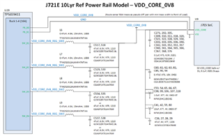
I am reading your paper "J721E 10Lyr Reference Design PCB Power Integrity Analysis".
The background is we found the VRM(R&L) setting in CAD tool(Hyperlynx) affecting PI result a lot.
So, in your case(J721E),
1. Does the effective resistance equal to the R in VRM setting?
2. Does the loop inductance equal to the L in VRM setting?
3. Do the VRM setting depend on all PMIC(TPS659411), caps and J721E?
4. How to get the R&L value? Please share your method with your CAD tool.
Thanks a lot.