This thread has been locked.

If you have a related question, please click the "Ask a related question" button in the top right corner. The newly created question will be automatically linked to this question.

PROCESSOR-SDK-AM62X: External UART communication using the pins TX (A5) and RX (B5)

Part Number: PROCESSOR-SDK-AM62X
Other Parts Discussed in Thread: SYSCONFIG

Tool/software:

Hello everyone,

I had an issue with UART pins of the M4F core (MCU_UART0_TXD_CONN, MCU_UART0_RXD_CONN).

I'm using code composer 12.7.1, Sysconfig 1.20.0, mcu_plus_sdk_am62x_09_02_01_00 and the board "EVM Sitara AM62x".

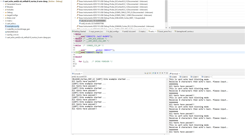
I used TI examples for UART (uart_echo, uart_echo_callback,...) but the external UART communication didn't work.

How to solve this problem ?

  • Hello Abdeltif,

    I am assuming you have a configuration(hardware Jumper connections) of atleast MCU UART TX(A5) to your receiver's RX pin.

    If that is the case, then a function like UART_write() should work and send the data over to the corresponding receiver's RX pin.

    Moreover we can run two sanity checks here. See when you call UART_write(), two possibilities are there:

    1. The data gets sent over to the receiver's RX Pin.

    2. Or the data gets sent over at pad/SoC level to the MCU_UART's RX pin.

    So can you run the sample UART echo example and let me know which one of the two functionalities is happening?

    Regards,

    Vaibhav

  • Hello Vaibhav,

    Thank you for your response.

    I am currently working on a UART loopback test, where I am sending data from the TX pin of the MCU UART to the RX pin of the same UART. I executed the sample UART echo example successfully, and I saw the expected message in the UART console:

    "This is uart echo test blocking mode Receives 8 characters then echo's back. Please input.." 12345678 All tests have passed!!

    However, I encountered an issue where I measured 0 current on both the TX and RX pins during this test.

    For your reference, I am using SD card boot mode.

    Could you please help me understand why the voltage measurement might be reading zero despite successful communication?

    Thank you for your assistance.

  • Hello Abdeltif,

    Thanks for your response.

    I am currently working on a UART loopback test, where I am sending data from the TX pin of the MCU UART to the RX pin of the same UART

    Yes this is what is already provided as a part of TI's SW MCU PLUS SDK examples.

    For your reference, I am using SD card boot mode.

    Thank you for stating the bootmode which you opted for.

    However, I encountered an issue where I measured 0 current on both the TX and RX pins during this test.

    Do you mean to say that you did not observe any voltage on the pins? Like let's say, if TX pin is configured for 3.3V then were you not able to see any voltage signal on the same?

    Can you also let me know if you are running uart echo application, then which one of the following it is?

    Looking forward to your response.

    Regards,

    Vaibhav

  • Hello Vaibhav,

    Yes, I didn't observe any voltage on the pins.

    Also, the example of GPIO LED blink works well for almost all the MCU header pins except UART pins.

    I'm working on the example of uart_echo application for the m4fss0-0_nortos.

    Thank you for your assistance.

  • Hello Abdeltif,

    I am going to then run the UART echo application and check for voltage and signals using logic analyzer.

    This might take sometime to go through as I have some other priority work upfront.

    Please ping here on the thread if you do not see any response by early next week.

    So my setup would mostly be:

    1. SD Card bootmode

    2. uart echo m4fs nortos example.

    3. Probing the TX pin and checking for signal.

    Regards,

    Vaibhav

  • Hello Vaibhav,

    Alright, I'll be waiting for your response.

    Thank you for your assistance.

  • Hello Abdeltif,

    Thank you for understanding.

    Regards,

    Vaibhav

  • Hello Vaibhav,

    Do you have any news regarding the UART pins issue?

    Looking forward to your response.

    Thank you for your assistance.

    BR,

  • Hello Abdeltif,

    Currently,  The subject matter expert is out of office. Please expect responses in several business days.

    Regards,

    Tushar

  • Hello Tushar,

    Alright, thank you for the information.

    BR,

  • Hello Abdeltif,

    I ran this on my setup and I am also not seeing any signals on the logic analyzer. I think because this is happening at the SoC level, hence we are not seeing any values while probing. Can you try a different UART pin? Like a main domain UART will also do.

    Regards,

    Vaibhav