This thread has been locked.

If you have a related question, please click the "Ask a related question" button in the top right corner. The newly created question will be automatically linked to this question.

Change AM1808 VPIF’s memory stuffing manner for RAW input?

Anonymous
Anonymous
Other Parts Discussed in Thread: AM1808

Hi,


I would like to ask a question on AM1808 VPIF.


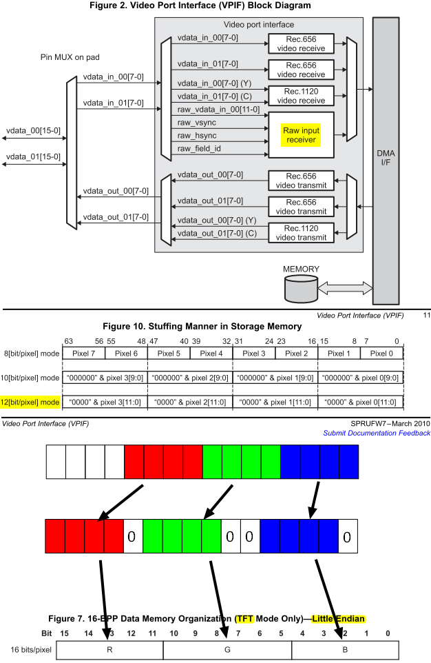
For 12-bit raw data input, the default memory storage format is shown in Fig.10. However,

1.    If I am using TFT LCD, does the TFT mode of LCDC support 12-bit format?

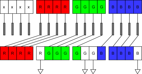
2.    If LCDC's TFT mode only supports 16-bit (video) format, then is it possible to convert the 12-bit data to RGB565 16-bit format, as shown in the picture below? Does AM1808 hardware support this padding and shifting process?


Zheng


  • Zheng,

    LCDC doesn't support 12-bit output in TFT mode.

    Zheng Zhao said:
    Does AM1808 hardware support this padding and shifting process?

    the LCDC HW doesn't support this feature. Does the ARM have enough BW left?


  • Anonymous
    0 Anonymous in reply to Paul.Yin

    Paul,

    Rather than shifting and padding bits for every single pixels on the fly, using processor, is it possible to simply "Sort" LCDC output Pins, like below?


    Zheng

  • Zheng,

    This is a very good idea. I like this trick. You are doing this when you are connecting to the LCD display right?

    You can either ground the unconnected pins, or tie the high to it. i.e., connect R3 to the Rground. You get more dynamic range this way.

    regards,

    Paul

  • Anonymous
    0 Anonymous in reply to Paul.Yin

    Paul,

    I am going to try it shortly after some other work. The validity of this trick is based upon the fast that the intended "processing" is just bit shifting, not multiplication or other operations. It is rather limited in use, but I think is a good solution to the present problem.

    What do you mean by R3? You mean "Red 3" in R7, R6, R5, R4, R3, R2, R1, R0, the firth pin from the left? What do you mean by Rground? Are you referring to just ground?

    By "more dynamic range", you mean the 0 or 8 (because R3 either 0 or 1) shift of range introduced in this way?


    Zheng


  • Anonymous
    0 Anonymous in reply to Paul.Yin

    Paul,


    Do you mean unconnected pins should be connected to the ground via a resistor? If they are connected high, should they also be connected via a resistor? If both are required, would 20K Ω be enough?


    Zheng


  • Zheng Zhao said:
    The validity of this trick is based upon the fast that the intended "processing" is just bit shifting, not multiplication or other operations.

    I am aware of that limitation. I still like your creativity.

    Zheng Zhao said:

    What do you mean by R3? You mean "Red 3" in R7, R6, R5, R4, R3, R2, R1, R0, the firth pin from the left? What do you mean by Rground? Are you referring to just ground?

    By "more dynamic range", you mean the 0 or 8 (because R3 either 0 or 1) shift of range introduced in this way?

    Sorry about the confusion. Since you are trying to connect RGB444 to RGB565 panel, I meant you can have Rlcdc[3:0] = Rpanel [4:1] and Rpanel[0] = Rlcdc[3]. This way you hit minimum & maximum brightness.

    Zheng Zhao said:

    Do you mean unconnected pins should be connected to the ground via a resistor? If they are connected high, should they also be connected via a resistor? If both are required, would 20K Ω be enough?


    what pins? the 4 output of LCDC that are don't cares? if you aren't using them for other functionality in other pinmux modes, i say just leave them floating.

  • Anonymous
    0 Anonymous in reply to Paul.Yin

    Paul,

    I haven't managed to make it work (pin sorting trick, RGB12 data format, RGB565 output) on DM6437. The pins outputs seems pretty weird. I am not sure whether it is related with transparency settings.

    Zheng


  • Zheng,

    I would first recommend you setup some dummy pattern in your memory. I.e., your data can be 0x0ABC, and see if you do see ABC on LCD_OUT[11:0].

    Go from there.

    regards,

    Paul

  • Anonymous
    0 Anonymous in reply to Paul.Yin

    Paul,

    Tried numerous dummy patterns, but still no "single component", i.e., cannot control to only output R/G/B component individually.


    Zheng

  • Zheng,

    What do you mean? If your data in the frame buffer is 0x0ABC, 0x0ABC, 0x0ABC,..., you never see 0x0ABC on your output [15:0]? then you have some setup issue.

    regards,

    Paul

  • Anonymous
    0 Anonymous in reply to Paul.Yin

    Paul,

    I just observed LCD display. However the better way seems to be using oscilloscope. I will do that.


    Zheng