Tool/software:
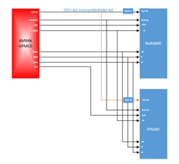
My GPMC using topology shows like this:

This thread has been locked.
If you have a related question, please click the "Ask a related question" button in the top right corner. The newly created question will be automatically linked to this question.
Hello
Thank you for the query.
The picture is not clear.
Please rpvide a clearer picture.
Regards,
Sreenivasa
Hello
Thank you for the updated picture.
Help me understand the signals you are considering the series resistors.
The max operating frequency may be a concern when the bus is interfaced to multiple devices and there could be layout challenges.
Regards,
Sreenivasa
Hello
The series resistors should be add? Is that better for SI?
Could help.
Start with 0R.
Performing simulations would be recommended.
Regards,
Sreenivasa
Hello,
Thank you.
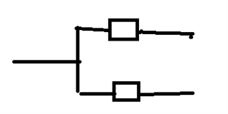
The recommendation is to shift the resistor after the T joint and add 2 resistors for signals that are shared and a single resistor for signals that are connected directly.
Regards,
Sreenivasa
hello
The suggestion would be to provide series resistor after the T joint for both input.
The T joint should be balanced.
The placement can be at the start of the joint if no simulations are performed. or can be placed based on the simulation results.
Regards,
Sreenivasa
Hello
Please refer below

For signals that does not have a T, add series resistor near to the source.
Regards,
Sreenivasa
Hello
Thank you.
The resistor will still be after the T Joint.
Place the resistor closer to the device that could see higher impedance mismatch.
This would require simulation or placing at the center between the SOC and the attached device.
Regards,
Sreenivasa
Hello,
Thank you.
For DATA(bi-direction signal),There contains following signal flow,is that the T joint resistor are avaliable for all signal flow?Thanks.
Please eloborate.
One of the devices is selected at a time. This is a general approach. Specific approach includes analysis/simulation.
Regards,
Sreenivasa
Hello
I would expect you to use 2 resistors any time there is a T.
The location of the resistor could be different for address, control and data.
The location depends on the design and analysis will be required.
Regards,
Sreenivasa
Hello
Please refer to the below section for the supported interfaces.
12.3.3.4.13.2.1 Supported Memories or Devices
Regards,
Sreenivasa
I found that,it seems that LSB is from A[0]
Does the GPMC support this NVRAM.datasheet attached,thanks for your patient.
Hello
I found that,it seems that LSB is from A[0]
Noted.
Does the GPMC support this NVRAM.datasheet attached,thanks for your patient.
We do not make part recommendations.
Regards,
Sreenivasa