This thread has been locked.

If you have a related question, please click the "Ask a related question" button in the top right corner. The newly created question will be automatically linked to this question.

AM62A7-Q1: Fail to cat in_illuminance_input from opt3001 driver

Part Number: AM62A7-Q1
Other Parts Discussed in Thread: OPT3001, , AM62A7, SYSCONFIG

Tool/software:

Dear Ti experts,

We are having problem fetching results from the opt3001 driver.

When trying to cat in_illuminance_input, the cat will result in timeout, regardless of the integration time:

With i2ctransfer we can read the registers from opt3001, here are the initial values:

with i2ctransfer the initial result from register 0x00 is 0x00 0x00, once in_illuminance_input is accessed, the result from register 0x00 will be refreshed:

We'd like to know what the problem is in the case. We didn't modify anything in the opt3001 driver, kept the related hardware design as before(the design worked fine), and can access the chip via i2c.

Regards,

Huang Jingjie

  • Hello Huang,

    I am sending your thread over to the opt3001 team to discuss how they expect their part to interact with a Linux processor. Please ping the thread if you do not get a response within a couple of business days.

    Regards,

    Nick

  • Hi Nick,

    We have a good news that by disabling interrupt in the device tree, the opt3001 driver works perfectly.

    With our previous setup, the driver will be waiting for this event and eventually reports the time out error.

    By reading the data sheet, I don't get the idea here, as interrupts are invoked when measured value exceeds the limit, how does it have anything to do with each read event?

    Regards,

    Huang Jingjie

  • Hello Jingjie,

    It seems that this error occurred because the interrupt generated by the sensor went unnoticed by the host system causing the kernel to eventually time out. Could you please share your dts (device tree source)?

    Thank you,

    Daniel Balmaceda

  • Hi Daniel,

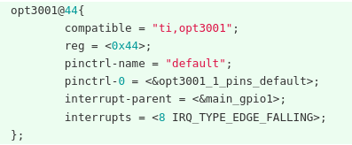
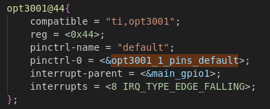
    The faulty case was with the following dts:

    The SOC pin B19 was connected to the INT pin of opt3001. According to our test, the pin was always low if active low of INT is set in the opt3001.

    We also tried to change the interrupt type to IRQ_TYPE_LEVEL_LOW, still the interrupt was not handled properly.

    Currently we are using it without the interrupt, and it works just fine. The problem might be caused by some hardware flaw. But again I want to ask:

    1. Why the sensor keeps generating interrupts in the first place? The default range was full range, so it was very unlikely for an out-of-range event to occur.  

    2. Why the read event has to rely on the interrupt indicating the range is exceeded?

    I hope these info are useful, and looking forward to your analysis.

    Regards,

    Huang Jingjie 

  • Hello Jingjie,

    We are currently working on recreating your setup with the OPT3001.

    1. The device should not be generating an interrupt if the high-limit and low-limit registers are not being exceeded. Are you defining anything within these registers?

    2. After each reading, the device then compares this to the high-limit and low-limit registers and generates an interrupt if these registers are being exceeded. This is just a characteristic of the device. In your case, whenever you do a device read, it looks like the device is reading a value that exceeds some threshold and is therefore generating an interrupt. However, your host system seems to not notice this interrupt and is timing out.

    Please allow some time to debug this setup.

    Thank you,

    Daniel Balmaceda

  • Hi Daniel,

    Thank you for the explaination. 

    We checked the 0x01 register with i2ctransfer, and the value was 0xc810, the default value in the datasheet. The range should be automatic full-scale so in theory no interrupt should be generated.

    This issue is only found in our 2nd design, in which the opt3001 is integrated in a standalone pcb and connect to the main pcb via fpc. I think we'd better check the hardware for possible flaw as well.

    Regards,

    Huang Jingjie

  • Hello Jingjie,

    Just wanted to update you with the status on this.

    After initial testing, it seems that there is a possible hardware issue on the interrupt pin. We will try to complete verification in the next two days.

    Thank you,

    Daniel Balmaceda

  • Hi Daniel,

    Sorry but we didn't have the time to further investigate the issue in the last few days.

    I double checked the hardware design as well as the device tree setup, and the faulty one is almost identical to the normal one, except that opt3001 is now on a separate pcb as I mentioned last time.

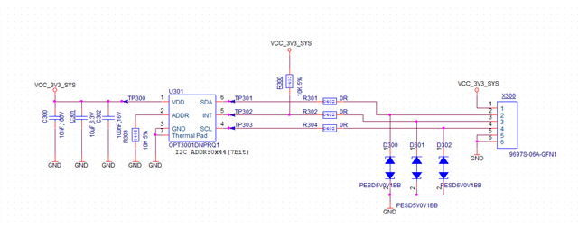
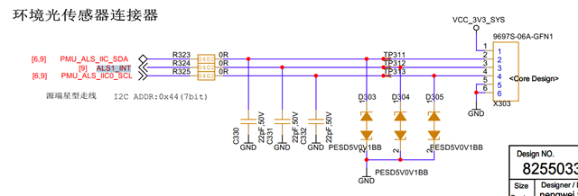
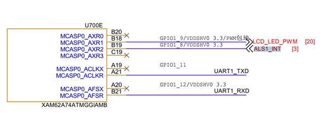
    Here are the details:

    opt3001 board:

    main board:

    device tree:

    One thing to notice is that if we do not provide interrupt setups in the device tree, the INT pin will always be high indicating no interrput is invoked, but if the setup is provided, the INT pin will always be low causing the timeout problem.

    It appears to me that the pinctrl is causing the problem, but this setup is working on the previous design. Do we need to change the PIN_INPUT into PIN_INPUT_PULLUP instead?

    Regards,

    Huang Jingjie

  • Hi Jingjie,

    It seems we are able to get the device to work using the DTS your provided. The pin not being pulled up could be a possible reason why the interrupt line is always low. Try changing the PIN_INPUT to PIN_INPUT_PULLUP.

    Thank you,

    Daniel Balmaceda

  • Hi Daniel,

    Thanks for the advice. Actually right after my last post, we tried the "PIN_INPUT_PULLUP" option, still the pin was dragged low.

    But since you can make it work with "PIN_INPUT", it suggests normally the pin should be functional with this setting.

    Anyway I'll ask our hardware engineer to further look into it.

    Regards,

    Huang Jingjie

  • Hi Jingjie,

    Could you please perform the following test without connecting to the interrupt pin and share your observation?

    1. Take lux value in normal condition (say reading is 200lux)
    2. Put some light (example: flash light of phone) and take reading (say reading is 400lux)
    3. Now move to events folder from current folder: cd /sys/bus/iio/devices/iio:device0/events
    4. Now change threshold high to 300lux (depends on your setup, value should be selected which can easy create threshold high jump: echo 300 | sudo tee in_illuminance_thresh_rising_value
    5. Please check threshold value is correct: cat in_illuminance_thresh_rising_value (it should return 300)
    6. Now enable continuous mode: echo 1 | sudo tee in_illuminance_thresh_rising_en
    7. Again check if continuous mode enabled: cat in_illuminance_thresh_rising_en (should return 1)
    8. Check in oscilloscope that INT pin line is high as you mentioned previously
    9. Now put flash light and check in oscilloscope that your interrupt line should be low as light sensor reading crossed threshold high (threshold high 300 lux< 400lux current reading)
    10. If no. 9 observation is happening then this is definitely dts interrupt configuration or h/w issue
    11. As in continuous mode you can't read value so make it disable: echo 0 | sudo tee in_illuminance_thresh_rising_en

    Thank you,

    Daniel Balmaceda

  • Hi Daniel,

    We just removed one of the resistor and run the test. Results are:

    1. In step 9, the interrupt pin on opt3001 was triggered as expected, indicating it was working as designed.

    2. On the other side, the level was low. It seems to me that once we setup the pin in the dts, it would be pulled low no matter what.

    As your previous reply mentioned, you are able to make opt3001 work normally with the dts details I provided, right? If that is the case, I'm directing the fault check to the hardware team entirely.

    Regards,

    Huang Jingjie

  • Hi Daniel,

    BTW in your test did you control the same pin, B19 GPIO1_8, as written in our dts? Could the problem come from this specific pin, though by reading the data sheet I think this is unlikely to be the cause? Our hardware team are doubting so I need to ask it here.

    Regards,

    Huang Jingjie

  • Hi Jingjie,

    Good to see the device is working as expected. A couple of more things:

    1. The INT pin will be low until you disable continuous mode: echo 0 | sudo tee in_illuminance_thresh_rising_en
    2. Please check if after this command INT pin level of opt3001 again goes up
    3. Can you check as opt3001 INT pin is set as output so INT pin of AM62A7-Q1 is set as input?


    As you mentioned that INT pin of opt3001 is not connected to hardware so can we perform test with interrupt (please enable interrupt in dts file)


    1. Please make sure continuous mode is disabled
    2. Connect INT pin of opt3001 with oscilloscope
    3. Please now try to read lux value: cat in_illuminance_input
    4. You should get active low after waiting for current integration time (100ms or 800ms)

    Thank you,

    Daniel Balmaceda

  • Hi Daniel,

    Thanks for the reply. In our test yesterday, INT pin was not connected to the SOC, and the behavior was exactly as you described.

    As for the second test, we can do it, but I think the key problem currently is that the GPIO in AM62A doesn't behave as expected. 

    Aside from B19, which is used as INT input for opt3001, we also tried some other pins, setting them as GPIO and providing the option PIN_INPUT_PULLUP. The weird thing is that none of them can be truely pulled up.

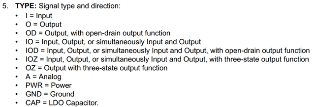
    While the datasheet doesn't explicitly write, I suppose the TYPE IO means the pin is in push-pull mode?

    The situation is a bit confusing right now, since I don't know whether the problem comes from the GPIO driver or hardware manufacturing. But apparently both the opt3001 and its linux driver are working as expected.

    Regards,

    Huang Jingjie

  • Hello Jingjie, 

    We have been using another linux processor we have on hand for our testing. From the DTS that you sent, I do not see anything wrong with your setup; however, I am not familiar with the AM62A7. Let me get back to you if I have any further suggestions. If not, you may need to refer back to the processors team.

    Thank you,

    Daniel Balmaceda

  • Hi Daniel,

    Thank you for the support and looking forward to more infomation.

    Regards,

    Huang Jingjie

  • Hi Jingjie,

    I am not entirely sure this is the problem; however, I do notice that you have 0x0198 as the pin address:

    However, in the recent image you sent me, it looks like the pin address is 0x00F4198:

    Other than that, I do not see a difference in how the interrupt is being configured. Try configuring it as:

    AM62AX_IOPAD(0x000F4198, PIN_INPUT_PULLUP, 7)

    Thank you,

    Daniel Balmaceda

  • Hi Daniel,

    The config is derived from sysconfig tool.

    Actually all of the GPIO pins in AM62a are configured via register 0x000F4XXX. I think they've must wrote the address calculation in the pin control driver so that only the last several bits are required in the pinctrl sentences.

    Regards,

    Huang Jingjie

  • Hi Jingjie,

    Since the device interrupt is working as expected, I will move this post to the processors forum so they can debug further.

    Thank you,
    Daniel Balmaceda

  • Hello Jingjie,

    It sounds like things are working now? Please restate the current question for the AM62Ax team, I am having trouble finding it in the previous responses.

    Regards,

    Nick

  • Hi Nick,

    Thank you for the response. I discussed a lot with Daniel and comfirmed that the OPT3001 is working as expected.

    The root cause of the problem now is that the GPIO setting in AM62A is misbehaving. While we try to set the pin B19 to be a GPI, no matter using PIN_INPUT or PIN_INPUT_PULLUP the pin was pulled low without the INT pin of opt3001 actually generating any interrupt.(The default interrupt for opt3001 is active low )

    The device tree setup is as follows:

    BTW the linux SDK version is 9.2. We tried to configure another pin and failed in the exact same way. 

    Regards,

    Huang Jingjie

  • Hello Huang,

    Got it, thanks for confirming. I am sending your thread to a team member to discuss GPIO setup - feel free to ping the thread if you do not get a response within a few business days.

    Regards,

    Nick

  • Hello Huang,

    Can you help me understand the expected behavior of the interrupt?

    Can you share the output of 'cat /proc/interrupts'? I want to see if the interrupt is enumerated by Linux. 

    Is ' #include <dt-bindings/interrupt-controller/irq.h>' added in the device tree? This include file allows for the use of interrupts. 


    Thanks,

    Anshu

  • Hi Anshu,

    Sorry for the late reply, I was onto some other issues.

    The expected behavior of the interrupt on opt3001 is that once the ambient light it sensed exceeds currently limit, it will pull the interrupt pin to low by default, so that certain function in its linux driver can be triggered to handle the situation.

    Privously we've tested that with default setting we cannot manually trigger this event, even if casting flash light directly onto the sensor, as the default limit is its full range.

    But the problem is that if we setup the pinctrl and register this interrupt, somehow the pin will be pulled low.

    The intterrupt is enumerated:

    The "#include <dt-bindings/interrupt-controller/irq.h>" is written in k3-am62a.dtsi, and this file is included in k3-am62a7-sk.dts, in which the opt3001 related configurations are written. I suppose this is okay?

    Regards,

    Huang Jingjie

  • Hello Huang,

    Can you confirm in Kernel config that module is enabled and loaded? Below is the path in menuconfig. After configuring the kernel, you'll have to rebuild the kernel: https://software-dl.ti.com/processor-sdk-linux/esd/AM62AX/09_02_00/exports/docs/linux/Foundational_Components_Kernel_Users_Guide.html#configuring-the-kernel

    When comparing your device tree to the Documentation (https://git.ti.com/cgit/ti-linux-kernel/ti-linux-kernel/tree/Documentation/devicetree/bindings/iio/light/ti,opt3001.yaml?h=ti-linux-6.1.y), I don't see clear issues.

    Where is &main_gpio1 node defined in the device tree? You could try moving the pinctrl-names & pinctrl-0 to main_gpio1.

    Thanks,

    Anshu

  • Hi Anshu,

    sorry for the late reply as we were having holidays. 

    The linux driver for opt3001 is enabled and loaded. As a matter of fact, we found this problem by "cat in_illumination_input", which is created by this very driver.

    By default the "main_gpio1" node is defined in k3-am62a-main.dtsi. The include relation, as I checked, is as follows:

    k3-am62a-main.dtsi included by k3-am62a.dtsi included by k3-am62a7.dtsi included by k3-am62a7-sk.dts. The last file has the node definition for opt3001, which I posted in the previous reply. I suppose this setup is correct?

    As for your last suggestion, I'll try it and reply the result ASAP.

    Regards,

    Huang Jingjie

  • Hello Huang,

    k3-am62a-main.dtsi included by k3-am62a.dtsi included by k3-am62a7.dtsi included by k3-am62a7-sk.dts. The last file has the node definition for opt3001, which I posted in the previous reply. I suppose this setup is correct?

    This should not be an issue. When the device tree is compiled, it combines all the other device tree includes (#include XYZ) into one larger compiled device tree called k3-am62a7-sk.dtb.

    Feel free to post on the thread when you have an update. I've been trying to find any other issues but nothing is apparent.

    Thanks,

    Anshu

  • Hi Anshu,
    I tried your idea but there is a problem:
    By changing pinctrl-0 to main_gpio1, the interrupt was not registered in the system, as nothing related can be seen in /proc/interrupts.
    Further more, nothing appeared under  /sys/bus/iio/devices/. In the normal case there should be something created by the driver, such as "in_illuminance_input", etc. Somehow the output of lsmod suggested that the opt3001 driver was probed and listed.
    I think this approach may not be correct. Other nodes in the device tree configure their pinctrl with standalone pin control nodes, in the same manner as we did with "opt3001_1_pins_default".

    Regards,

    Huang Jingjie

  • Hello Huang,

    Thanks for the update. I don't know anything about the 'in_illuminance_input' but from searching around, it seems to be related to tsl2583.
    Here are a few links I found:

    Best Regards,

    Anshu

  • Hi Anshu,

    'in_illuminance_input' is a interface registered by opt3001 driver, it is for user space to access opt3001 result.

    The fact is that when using main_gpio1 in pinctrl-0, the driver didn't register this interface, indicating that the configuration is wrong and the driver is not working as designed.

    So this issue have nothing to do with tsl2583.

    Regards,

    Huang Jingjie

  • Hello Huang,

    Thank you for clarifying this. What directory are you using 'cat' in?

    After looking through this, I'm not seeing any clear issues. You can also try decompiling the dtb to see if the node is being discovered correctly.

    If /sys/bus/iio/devices/ isn't populating, its either the driver is not being loaded or the something else in the device tree. Even if there is an issue with the interrupt, I would expect it to populate.

    Thanks,

    Anshu

  • Hi Anshu,

    Normally "in_illuminance_input", along with other interfaces, would be registered in /sys/bus/iio/devices/iio:device0.

    The driver was loaded since we can find it in the output of lsmod. Somehow the driver had some issue, but one thing for sure is that there was no problem in the i2c transmition, as most of the dev_err in the driver were about failing to read/write registers via i2a and none of them was shown in the dmesg.

    So far the difference among approaches can be summarised as follows:

    1. Without pinctrl and interrupt setup: opt3001 driver works as expected.

    2. With following setup: opt3001 driver is registered correctly, when trying to cat in_illuminance_input, the driver reports "read error: connection timed out". The pin was pulled low but not by opt3001, causing problem.

    3. With following setup: opt3001 driver is not registerde correctly, no interface for user access, as described in the previous replys.

    Key problem now is, once the interrupt is registered, the pin would be pulled low, but not by opt3001. As mentioned before, we tried "PIN_INPUT" as well as "PIN_INPUT_PULLUP" with no luck.

    Regards,

    Huang Jingjie

  • Hi Huang,

    I'll try to replicate this on my end but its difficult without access to the OPT3001 device. I'll let you know if I have any updates.

    Thanks,

    Anshu

  • Hi Anshu,

    I think the problem is not so relevant to opt3001. Whatever the target device is, as long as the GPIO setting is working as expected, the problem could be solved. In the case of OPT3001, this GPIO has to be a INPUT and its default Level should be high.

    Regards,

    Huang Jingjie