This thread has been locked.

If you have a related question, please click the "Ask a related question" button in the top right corner. The newly created question will be automatically linked to this question.

AM6442: GPIO-interrupt example fails to start.

Part Number: AM6442
Other Parts Discussed in Thread: SYSCONFIG

Tool/software:

 Hi,

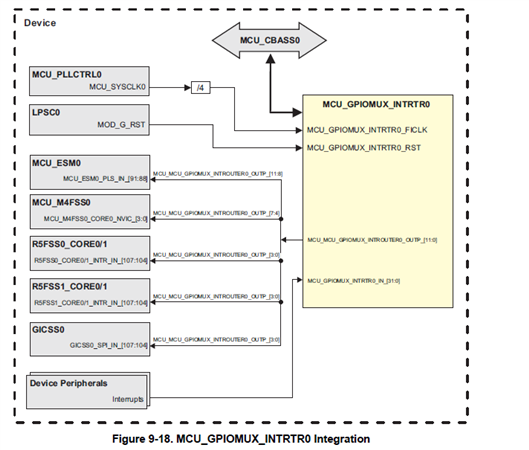
I'm looking to extend a firmware application that's been in development a little while with an GPIO-interrupt counter mechanism. Note that this firmware is running on the R5F0_0 core while Linux is active on the A53 cores. To have an initial test of the HAL API related to GPIO-interrupts I tried the "gpio_interrupt_am64x-evm_r5fss0-0_nortos_ti-arm-clang"-example by loading it in CCS and deploying it through the XDS110 on-board debug probe. The example firmware loads correctly (i.e. enters main) but halts in an assert failure that fires in the "void Module_clockSetFrequency(void)"-function in "ti_power_clock_config.c". See call stack below:

_DebugP_assertNoLog() at DebugP_log.c:119 0x700A286C
Module_clockSetFrequency() at ti_power_clock_config.c:99 0x7008FC40
PowerClock_init() at ti_power_clock_config.c:107 0x70092D0A
System_init() at ti_drivers_config.c:235 0x7009170C
main() at main.c:42 0x700922AE
bypass_auto_init + 0x4 () at boot_armv7r_asm.S:257 0x700A2828

This assert is the result of the "SOC_moduleSetClockFrequency(...)"-call returning -1. The value of "i" in the iteration that failed is 0.
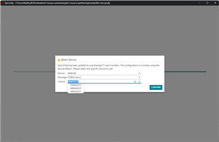
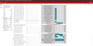
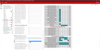
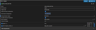
The sysconfig file that came with the example has been unchanged, except the pin the interrupt is set to. This has been changed to the "MCU_SPI1_CLK/D7"-pin. As this is the pin I intend to use in the main project.

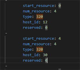
To prevent conflict in access to this pin from Linux, the device tree that is active in the kernel has:
&mcu_gpio0status = "reserved"; };
&
mcu_gpio_intr { status = "reserved";};
added to it. As per documentation https://software-dl.ti.com/mcu-plus-sdk/esd/AM64X/latest/exports/docs/api_guide_am64x/EXAMPLES_DRIVERS_GPIO_INPUT_INTERRUPT.html

The example is built with version 9.1.0.41 of the MCU+SDK if that helps.
I am unsure how the example is still breaking. Any advice on how to resolve this and get GPIO-interrupts working would be appreciated.

Kind regards,
Matthijs

  • Hi Matthijs,

    Thanks for your query.

    Can you please check for which module id the SOC_moduleSetClockFrequency() API is failing?

    My guess is it might be failing while setting frequency for UART as UART is already initialized by the Linux running on A53.

    Regards,

    Tushar

  • Hi Tushar,

    Sorry for the late response, I was out of office for a while.

    Your guess was correct! Changing the UART instance from UART0 to UART1 (Which I am also using in the main firmware project, silly I hadn't checked that peripheral's configuration) fixed this specific assert. The "moduleId"-argument to the "SOC_moduleSetClockFrequency"-function was 146.

    The example still fails to start though. Now hitting the same assert I encountered in the main firmware project. Call stack:

    _DebugP_assert() at DebugP_log.c:105 0x7008E7AE        

    Sciclient_gpioIrqSet() at ti_drivers_config.c:118 0x7008D97C        

    Board_gpioInit() at ti_drivers_config.c:78 0x70092D86        

    gpio_input_interrupt_main() at gpio_input_interrupt.c:72 0x700877E6        

    main() at main.c:46 0x700922B8        

    bypass_auto_init + 0x4 () at boot_armv7r_asm.S:257 0x700A2828

    The assert failure is caused by a failure-return from the "Sciclient_rmIrqSet"-function. The request structure is built as follows:

    rmIrqReq.valid_params           = 0U;
        rmIrqReq.valid_params          |= TISCI_MSG_VALUE_RM_DST_ID_VALID;
        rmIrqReq.valid_params          |= TISCI_MSG_VALUE_RM_DST_HOST_IRQ_VALID;
        rmIrqReq.global_event           = 0U;
        rmIrqReq.src_id                 = TISCI_DEV_MCU_GPIO0;
        rmIrqReq.src_index              = TISCI_BANK_SRC_IDX_BASE_MCU_GPIO0 + GPIO_GET_BANK_INDEX(7);
        rmIrqReq.dst_id                 = TISCI_DEV_R5FSS0_CORE0;
        rmIrqReq.dst_host_irq           = CSLR_R5FSS0_CORE0_INTR_MAIN_GPIOMUX_INTROUTER0_OUTP_0;
        rmIrqReq.ia_id                  = 0U;
        rmIrqReq.vint                   = 0U;
        rmIrqReq.vint_status_bit_index  = 0U;
        rmIrqReq.secondary_host         = TISCI_MSG_VALUE_RM_UNUSED_SECONDARY_HOST;

    And the response structure's header has the following contents:

    type: 11592

    host: 10

    seq: 112

    flags: 0

    Is there something wrong with how this request structure is formed? The src_id/index values seem to make sense considering I configured MCU_GPIO0_7 as the pin to check interrupts on.

    Kind regards,

    Matthijs

  • Hi Matthijs,

    Can you please check the TISCI_DEV_MCU_GPIOMUX_INTROUTER0(i.e. type: 320) entries in the rm-cfg.yaml file present at path ${SDK}/board-support/ti-u-boot-<version>/board/ti/am64x?

    From the above image I can see that the TISCI_DEV_MCU_GPIOMUX_INTROUTER0 is only allocated to host id 30 and 12 which belongs to M4_0 and A53_2 respectively. You will need to allocate the interrupt router to R5F core before configuring it.

    To configure resource please refer faq-how-to-use-k3-resource-partitioning-tool-with-processor-sdk-v9-0-or-v9-1 for more details.

    Regards,

    Tushar

  • Hi Tushar,

    Really appreciate the quick follow-up. Thanks for that.

    I am following the instructions you linked and am running sysconfig from the "k3-resource-partitioning"-folder. Starting this and loading the "k3-resource-partitioning/out/am64x-evm.syscfg presented me with a menu with a "Variant" option.

    What does this "Variant" refer to? The AM64x user guide has a section on "Revisions and Assembly Variants" but does not mention a D, E, or F label.

    I did find in the Technical reference manual under "Revision history" mention "Changes from July 18, 2023 to October 31, 2023 (from Revision G (July 2023) to Revision H (October 2023))"

    I am going with the default setting here but is there is a "more correct" variant to select here?

    Also, is this default/initial sysconfig that I am loading also the one my "out of the box" bootloader was built with? Or is there a chance at regressions in other settings if I build a new uboot bin file with this change?

    Finally, I am unsure how to make the relevant configuration change you describe. I did find the setting "MCU GPIO Interrupt Router Count" in the tool. But should I give the R5F core access to it by adding a "Resource Sharing" module/instance from either the M4_0 or A53_2 core? Or should I add increment the "MCU GPIO Interrupt Router Count" setting under the MAIN_0_R5_1 tab? as shown here:

    Note that I also changed the router count in the other cores from 4 to 2. As not doing that while increasing the router count on the 0_R5_1 core caused gave the error:

    Again, greatly appreciate the help so far, though I would like to be really sure of the changes I am applying here as I don't want to break my development setup. Slight smile

    Kind regards,

    Matthijs

  • Hi Matthijs,

    What does this "Variant" refer to? The AM64x user guide has a section on "Revisions and Assembly Variants" but does not mention a D, E, or F label.

    To get the above information please refer to the section Device Naming Convention device specific datasheet.

    Also, is this default/initial sysconfig that I am loading also the one my "out of the box" bootloader was built with? Or is there a chance at regressions in other settings if I build a new uboot bin file with this change?

    Sorry, I don't understand the above statement clearly. But I think you are asking is the am64x-evm.syscfg file provided in k3-resource-partitioning tool represents the resources which are currently allocated. The answer is yes, it is representing the currently allocated resources.

    Finally, I am unsure how to make the relevant configuration change you describe. I did find the setting "MCU GPIO Interrupt Router Count" in the tool. But should I give the R5F core access to it by adding a "Resource Sharing" module/instance from either the M4_0 or A53_2 core? Or should I add increment the "MCU GPIO Interrupt Router Count" setting under the MAIN_0_R5_1 tab? as shown here:

    From the TRM, I can see that the MCU_GPIOMUX_ROUTER [0:3] is connected to both the A53 and R5F core.

    So you can share the MCU_GPIOMUX_ROUTER between both A53 and R5F.

    Please refer below image.

    To share the resources, please do below changes in resource partition.

    Go to resource sharing, add a new sharing option and configure it according to the below parameters.

    Save the rm-cfg.yaml file and follow the steps mentioned in the above FAQ.

    Please let us know if the above solution works.

    Regards,

    Tushar

  • Hi Tushar,

    I did save the new .yaml-file as instructed. Appreciate the screenshots.

    The one step that fails however is building uboot. When running the given command in my SDK I get the following output:

    ~/ti-processor-sdk-linux-am64xx-evm-09.00.00.03/board-support/ti-u-boot$ make u-boot

    scripts/kconfig/conf  --syncconfig Kconfig

    ***

    *** Configuration file ".config" not found!

    ***

    *** Please run some configurator (e.g. "make oldconfig" or

    *** "make menuconfig" or "make xconfig").

    ***

    make[2]: *** [scripts/kconfig/Makefile:75: syncconfig] Error 1

    make[1]: *** [Makefile:575: syncconfig] Error 2

    make: *** No rule to make target 'include/config/auto.conf', needed by 'include/config/uboot.release'.  Stop.

    When needing to build the Linux kernel for device tree binaries I used to do "make menuconfig", then exiting to save the default config that it created. Would that also work here? After which I can run the "make u-boot" command? Or would a more elaborate config be needed? Like the "SD boot" defconfig options documented here?

    And follow up question on the instructions given above, I would only need the "R5" binary right? As that in the comment is called "tiboot3.bin". Which is the file I need according to the FAQ...?

    Regards,

    Matthijs

  • Update,

    I followed the complete instructions in my earlier comment.
    For setup I had to install the "python3-jsonschema" and "swig" packages.
    For toolchain I exported the gcc instances from the external-toolchain-dir:

    export PATH=$PATH:$PWD/external-toolchain-dir/arm-gnu-toolchain-11.3.rel1-x86_64-aarch64-none-linux-gnu/bin

    export PATH=$PATH:$PWD/external-toolchain-dir/arm-gnu-toolchain-11.3.rel1-x86_64-arm-none-linux-gnueabihf/bin

    For dependencies I cloned and checked out the necessary repositories, exporting them as:

    export UBOOT_DIR=$HOME/repos/am64_development/ti-u-boot
    export TI_LINUX_FW_DIR=$HOME/repos/am64_development/ti-linux-firmware
    export TFA_DIR=$HOME/repos/am64_development/trusted-firmware-a
    export OPTEE_DIR=$HOME/repos/am64_development/optee_os

    During compilation it stated:

     Using /home/matthijs/ti-processor-sdk-linux-am64xx-evm-09.00.00.03/board-support/ti-u-boot as source for U-Boot

    And under those sources I placed the updated rm-cfg.yaml.

    After compilation it outputted the "tiboot3.bin" file under $UBOOT_DIR/out/r5 as expected.

    What I am curious about is if I can validate without deploying that the changed configuration is applied. I noticed an "rm-cfg.map" file that contains the following:

    ImagePos    Offset      Size  Name
    00000000  00000000  0000067e  rm-cfg
    00000000   00000000  0000067e  ti-board-config
    

    Unsure if this is correct.

  • Hi Matthijs,

    What I am curious about is if I can validate without deploying that the changed configuration is applied. I noticed an "rm-cfg.map" file that contains the following:

    Not sure if I got your point fully or not. But I think you want to check whether new tiboot3.bin is generated with the updated changes or is it still having the previously allocated resources. I have never done this comparison.

    But If somehow you can compare the binaries of the older and newer tiboot3.bin, you will be able to confirm whether the changes are done or not.

    The other way is just to boot the EVM with updated images and run the k3conf tool to dump the resources.

    Run the below command from EVM's Linux user shell. 

    k3conf dump rm

    Regards,

    Tushar

  • Hi Tushar,

    Thanks for sharing that utility command. I recorded the output of those dumps before and after applying the tiboot3.bin file to the system. Here is the diff between the two:

    On the right is the newly built one, the left is the previous one. I believe this output has the desired change applied. With the "resource utype"-field 0x140 being the "type: 320" field in the yaml shared earlier.

    I am unsure if the "SYSFW ABI"-field being newer is an issue. The board booted completely and the firmware started as normal.
    It did not resolve the assert however. When running either my main project or the example. Both still assert in the startup.

    I tried changing the:

       rmIrqReq.dst_host_irq           = CSLR_R5FSS0_CORE0_INTR_MAIN_GPIOMUX_INTROUTER0_OUTP_0;

    line from ...OUTP_0 (32)  to "CSLR_R5FSS0_CORE1_INTR_MAIN_GPIOMUX_INTROUTER0_OUTP_4" (36) to be consistent with the "host_id" value in rm_cfg.yaml. Though this also did not resolve the assert.

    Is there something else wrong with the GPIO sysconfig settings?

    Kind regards,

    Matthijs

  • Hi Matthijs,

    I can see you are generating interrupt for MCU_GPIOMUX_ROUTER and configuring MAIN_GPIOMUX_ROUTER.

    Can you please try configuring CSLR_R5FSS0_CORE0_INTR_MCU_MCU_GPIOMUX_INTROUTER0_OUTP_0 router output as dst_host_irq?

    Use the below configuration.

    rmIrqReq.src_id                 = TISCI_DEV_MCU_GPIO0;
    rmIrqReq.src_index              = TISCI_BANK_SRC_IDX_BASE_MCU_GPIO0 + GPIO_GET_BANK_INDEX(7);
    rmIrqReq.dst_id                 = TISCI_DEV_R5FSS0_CORE0;
    rmIrqReq.dst_host_irq           = CSLR_R5FSS0_CORE0_INTR_MCU_MCU_GPIOMUX_INTROUTER0_OUTP_0;

    Please let us know if the above solution works.

    Regards,

    Tushar

  • Hi Tushar,

    Good news, that configuration change fixes the assert-crash! So the interrupt example continues executing and starts printing "Key is pressed 0 times". The bad news is that the interrupt is not detected. The count never increments as I trigger a state change on the pin.

    I did validate that wiring is correct through polling. When polling in a loop the pin-state change is properly detected. So I don't think this issue is physical.

    I changed the functions declared extern to:

    static void GPIO_interrupt_deinit()
    {
        int32_t                             retVal;
        struct tisci_msg_rm_irq_release_req rmIrqReq;
        rmIrqReq.valid_params           = 0U;
        rmIrqReq.valid_params          |= TISCI_MSG_VALUE_RM_DST_ID_VALID;
        rmIrqReq.valid_params          |= TISCI_MSG_VALUE_RM_DST_HOST_IRQ_VALID;
        rmIrqReq.global_event           = 0U;
        rmIrqReq.src_id                 = TISCI_DEV_MCU_GPIO0;
        rmIrqReq.src_index              = TISCI_BANK_SRC_IDX_BASE_MCU_GPIO0 + GPIO_GET_BANK_INDEX(7);
        rmIrqReq.dst_id                 = TISCI_DEV_R5FSS0_CORE0;
        rmIrqReq.dst_host_irq           = CSLR_R5FSS0_CORE0_INTR_MCU_MCU_GPIOMUX_INTROUTER0_OUTP_0;
        rmIrqReq.ia_id                  = 0U;
        rmIrqReq.vint                   = 0U;
        rmIrqReq.vint_status_bit_index  = 0U;
        rmIrqReq.secondary_host         = TISCI_MSG_VALUE_RM_UNUSED_SECONDARY_HOST;
    
        retVal = Sciclient_rmIrqRelease(&rmIrqReq, SystemP_WAIT_FOREVER);
        if(0 != retVal)
        {
            DebugP_log("[Error] Sciclient event reset failed!!!\r\n");
            DebugP_assert(FALSE);
        }
        return;
    }
    
    void GPIO_interrupt_init()
    {
        int32_t                             retVal;
        struct tisci_msg_rm_irq_set_req     rmIrqReq;
        struct tisci_msg_rm_irq_set_resp    rmIrqResp;
        rmIrqReq.valid_params           = 0U;
        rmIrqReq.valid_params          |= TISCI_MSG_VALUE_RM_DST_ID_VALID;
        rmIrqReq.valid_params          |= TISCI_MSG_VALUE_RM_DST_HOST_IRQ_VALID;
        rmIrqReq.global_event           = 0U;
        rmIrqReq.src_id                 = TISCI_DEV_MCU_GPIO0;
        rmIrqReq.src_index              = TISCI_BANK_SRC_IDX_BASE_MCU_GPIO0 + GPIO_GET_BANK_INDEX(7);
        rmIrqReq.dst_id                 = TISCI_DEV_R5FSS0_CORE0;
        rmIrqReq.dst_host_irq           = CSLR_R5FSS0_CORE0_INTR_MCU_MCU_GPIOMUX_INTROUTER0_OUTP_0;
        rmIrqReq.ia_id                  = 0U;
        rmIrqReq.vint                   = 0U;
        rmIrqReq.vint_status_bit_index  = 0U;
        rmIrqReq.secondary_host         = TISCI_MSG_VALUE_RM_UNUSED_SECONDARY_HOST;
    
        retVal = Sciclient_rmIrqSet(&rmIrqReq, &rmIrqResp, SystemP_WAIT_FOREVER);
        if(0 != retVal)
        {
            DebugP_log("[Error] Sciclient event config failed!!!\r\n");
            DebugP_assert(FALSE);
        }
        return;
    }

    This is to prevent sysconfig from overriding the fix you suggested when rebuilding the firmware.

    I'll test further on my end to see if I can figure out why the interrupt is not triggered.

    Kind regards,

    Matthijs

  • Update,

    Got the final fix that made the example work!

    The issue was in the initial assignment of the "intrNum"-variable. This was initially taken from a function generated through sysconfig. The value for this was still a MAIN_GPIOMUX-interrupt number. Having changed it to the value of "CSLR_R5FSS0_CORE0_INTR_MCU_MCU_GPIOMUX_INTROUTER0_OUTP_0" makes it all work

    GPIO Interrupt Configured for Rising Edge (Button release will trigger interrupt) ...
    Press and release SW5 button on EVM to trigger GPIO interrupt ...
    Key is pressed 0 times
    Key is pressed 0 times
    Key is pressed 0 times
    Key is pressed 29 times
    GPIO Input Interrupt Test Passed!!
    All tests have passed!!

    Thanks for all the help!

    Matthijs