

Tool/software:
I want to toggle a GPIO or toggle a LED from the U-Boot Prompt. How can I do this?

This thread has been locked.
If you have a related question, please click the "Ask a related question" button in the top right corner. The newly created question will be automatically linked to this question.
Tool/software:
I want to toggle a GPIO or toggle a LED from the U-Boot Prompt. How can I do this?
Steps Required:
For this example, GPIO0_14 will be used on Linux SDK 9.2: https://www.ti.com/tool/download/PROCESSOR-SDK-LINUX-AM62X
Below are diffs for the U-Boot and Linux Device Trees.
#Linux Device Tree
diff --git a/arch/arm64/boot/dts/ti/k3-am62x-sk-common.dtsi b/arch/arm64/boot/dts/ti/k3-am62x-sk-common.dtsi
index b1980b85c..9d611d5de 100644
--- a/arch/arm64/boot/dts/ti/k3-am62x-sk-common.dtsi
+++ b/arch/arm64/boot/dts/ti/k3-am62x-sk-common.dtsi
@@ -178,6 +178,12 @@ hdmi_connector_in: endpoint {
 };

 &main_pmx0 {
+       maingpio0_pins_default: maingpio0-default-pins {
+               pinctrl-single,pins = <
+                       AM62X_IOPAD(0x0038, PIN_INPUT, 7) /* (E24) OSPI0_CSn3.GPIO0_14 */
+               >;
+       };
+
        /* First pad number is ALW package and second is AMC package */
        main_uart0_pins_default: main-uart0-pins-default {
                pinctrl-single,pins = <
@@ -329,6 +335,12 @@ AM62X_IOPAD(0x0078, PIN_OUTPUT, 1) /* (U24) GPMC0_AD15.VOUT0_DATA23 */
        };
 };

+&main_gpio0{
+       status = "okay";
+       pinctrl-names = "default";
+       pinctrl-0 = <&maingpio0_pins_default>;
+};
+
 &wkup_uart0 {
        /* WKUP UART0 is used by DM firmware */
        status = "reserved";
#U-Boot Device Tree
diff --git a/arch/arm/dts/k3-am62x-sk-common.dtsi b/arch/arm/dts/k3-am62x-sk-common.dtsi
index 209114c8..215e60e1 100644
--- a/arch/arm/dts/k3-am62x-sk-common.dtsi
+++ b/arch/arm/dts/k3-am62x-sk-common.dtsi
@@ -119,6 +119,12 @@
 };

 &main_pmx0 {
+       maingpio0_pins_default: maingpio0-default-pins {
+               pinctrl-single,pins = <
+                       AM62X_IOPAD(0x0038, PIN_INPUT, 7) /* (E24) OSPI0_CSn3.GPIO0_14 */
+               >;
+       };
+
        /* First pad number is ALW package and second is AMC package */
        main_uart0_pins_default: main-uart0-pins-default {
                pinctrl-single,pins = <
@@ -221,6 +227,12 @@
        };
 };

+&main_gpio0{
+       status = "okay";
+       pinctrl-names = "default";
+       pinctrl-0 = <&maingpio0_pins_default>;
+};
+
 &wkup_uart0 {
        /* WKUP UART0 is used by DM firmware */
        status = "reserved";
There is one added node for the PinMuxing definition and another node for the reference. Both diffs are identical because the PinMux has to match both device trees.
Follow the SDK documentation for building both of these device trees and installing the new images onto the boot method.
Linux Documentation: https://software-dl.ti.com/processor-sdk-linux/esd/AM62X/09_02_01_10/exports/docs/linux/Foundational_Components_Kernel_Users_Guide.html#preparing-to-build
U-Boot Documentation: https://software-dl.ti.com/processor-sdk-linux/esd/AM62X/09_02_01_10/exports/docs/linux/Foundational_Components/U-Boot/UG-General-Info.html#build-u-boot
From SDK 9.0 and onward, the GPIO commands will be included in the pre-built images that come with the SDK (<SDK Install Path>/board-support/prebuilt-images/<device>/).
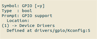
If not, enable the GPIO commands in the config file, following the instructions in the SDK Documentation.
Boot the device and stop at the U-Boot Command Prompt.
U-Boot SPL 2023.04-dirty (Aug 09 2024 - 16:10:17 -0500)
SYSFW ABI: 3.1 (firmware rev 0x0009 '9.2.7--v09.02.07 (Kool Koala)')
SPL initial stack usage: 13408 bytes
Trying to boot from MMC2
Authentication passed
Authentication passed
Authentication passed
Authentication passed
Authentication passed
Starting ATF on ARM64 core...

NOTICE:  BL31: v2.10.0(release):v2.10.0-367-g00f1ec6b87-dirty
NOTICE:  BL31: Built : 16:09:05, Feb  9 2024

U-Boot SPL 2023.04-dirty (Aug 09 2024 - 16:10:26 -0500)
SYSFW ABI: 3.1 (firmware rev 0x0009 '9.2.7--v09.02.07 (Kool Koala)')
SPL initial stack usage: 1856 bytes
Trying to boot from MMC2
Authentication passed
Authentication passed


U-Boot 2023.04-dirty (Aug 09 2024 - 16:10:26 -0500)

SoC:   AM62X SR1.0 HS-FS
Model: Texas Instruments AM625 SK
EEPROM not available at 80, trying to read at 81
Board: AM62B-SKEVM-P1 rev A
DRAM:  2 GiB
Core:  74 devices, 34 uclasses, devicetree: separate
MMC:   mmc@fa10000: 0, mmc@fa00000: 1
Loading Environment from nowhere... OK
In:    serial
Out:   serial
Err:   serial
Net:   eth0: ethernet@8000000port@1
Hit any key to stop autoboot:  0
=>
'gpio status -a' will print out all the available GPIOs.
=> gpio status -a
Bank gpio@4201000_:
gpio@4201000_0: input: 0 [ ]
gpio@4201000_1: input: 0 [ ]
gpio@4201000_2: input: 0 [ ]
gpio@4201000_3: input: 0 [ ]
gpio@4201000_4: input: 0 [ ]
gpio@4201000_5: input: 1 [ ]
gpio@4201000_6: input: 0 [ ]
gpio@4201000_7: input: 0 [ ]
gpio@4201000_8: input: 0 [ ]
gpio@4201000_9: input: 1 [ ]
gpio@4201000_10: input: 0 [ ]
gpio@4201000_11: input: 1 [ ]
gpio@4201000_12: input: 0 [ ]
gpio@4201000_13: input: 0 [ ]
gpio@4201000_14: input: 0 [ ]
gpio@4201000_15: input: 0 [ ]
gpio@4201000_16: input: 0 [ ]
gpio@4201000_17: input: 1 [ ]
gpio@4201000_18: input: 1 [ ]
gpio@4201000_19: input: 1 [ ]
gpio@4201000_20: input: 1 [ ]
gpio@4201000_21: input: 0 [ ]
gpio@4201000_22: input: 0 [ ]
gpio@4201000_23: input: 0 [ ]

Bank gpio@22_:
gpio@22_0: input: 1 [ ]
gpio@22_1: input: 1 [ ]
gpio@22_2: input: 1 [ ]
gpio@22_3: output: 1 [ ]
gpio@22_4: input: 0 [ ]
gpio@22_5: input: 0 [ ]
gpio@22_6: input: 0 [ ]
gpio@22_7: input: 1 [ ]
gpio@22_8: input: 1 [ ]
gpio@22_9: input: 1 [ ]
gpio@22_10: input: 1 [ ]
gpio@22_11: input: 1 [ ]
gpio@22_12: input: 1 [ ]
gpio@22_13: input: 0 [ ]
gpio@22_14: input: 0 [ ]
gpio@22_15: input: 0 [ ]
gpio@22_16: input: 1 [ ]
gpio@22_17: input: 0 [ ]
gpio@22_18: input: 0 [ ]
gpio@22_19: input: 0 [ ]
gpio@22_20: input: 1 [ ]
gpio@22_21: input: 1 [ ]
gpio@22_22: input: 1 [ ]
gpio@22_23: input: 0 [ ]

Bank gpio@600000_:
gpio@600000_0: output: 0 [ ]
gpio@600000_1: output: 0 [ ]
gpio@600000_2: output: 0 [ ]
gpio@600000_3: output: 1 [ ]
gpio@600000_4: output: 1 [ ]
gpio@600000_5: output: 1 [ ]
gpio@600000_6: output: 1 [ ]
gpio@600000_7: output: 1 [ ]
gpio@600000_8: output: 1 [ ]
gpio@600000_9: output: 1 [ ]
gpio@600000_10: output: 1 [ ]
gpio@600000_11: output: 0 [ ]
gpio@600000_12: output: 0 [ ]
gpio@600000_13: output: 0 [ ]
gpio@600000_14: output: 1 [ ]
gpio@600000_15: output: 1 [ ]
gpio@600000_16: output: 1 [ ]
gpio@600000_17: output: 1 [ ]
gpio@600000_18: output: 1 [ ]
gpio@600000_19: output: 1 [ ]
gpio@600000_20: output: 1 [ ]
gpio@600000_21: output: 1 [ ]
gpio@600000_22: output: 1 [ ]
gpio@600000_23: output: 0 [ ]
gpio@600000_24: output: 0 [ ]
gpio@600000_25: output: 0 [ ]
gpio@600000_26: output: 0 [ ]
gpio@600000_27: output: 0 [ ]
gpio@600000_28: output: 0 [ ]
gpio@600000_29: output: 0 [ ]
gpio@600000_30: output: 0 [ ]
gpio@600000_31: output: 0 [ ]
gpio@600000_32: input: 0 [ ]
gpio@600000_33: input: 0 [ ]
gpio@600000_34: input: 0 [ ]
gpio@600000_35: input: 1 [ ]
gpio@600000_36: input: 0 [ ]
gpio@600000_37: input: 1 [ ]
gpio@600000_38: input: 0 [ ]
gpio@600000_39: input: 0 [ ]
gpio@600000_40: input: 0 [ ]
gpio@600000_41: input: 0 [ ]
gpio@600000_42: input: 0 [ ]
gpio@600000_43: input: 1 [ ]
gpio@600000_44: input: 1 [ ]
gpio@600000_45: input: 0 [ ]
gpio@600000_46: input: 0 [ ]
gpio@600000_47: input: 0 [ ]
gpio@600000_48: input: 0 [ ]
gpio@600000_49: input: 0 [ ]
gpio@600000_50: input: 0 [ ]
gpio@600000_51: input: 0 [ ]
gpio@600000_52: input: 0 [ ]
gpio@600000_53: input: 0 [ ]
gpio@600000_54: input: 0 [ ]
gpio@600000_55: input: 0 [ ]
gpio@600000_56: input: 0 [ ]
gpio@600000_57: input: 0 [ ]
gpio@600000_58: input: 0 [ ]
gpio@600000_59: input: 0 [ ]
gpio@600000_60: input: 0 [ ]
gpio@600000_61: input: 0 [ ]
gpio@600000_62: input: 0 [ ]
gpio@600000_63: input: 0 [ ]
gpio@600000_64: input: 0 [ ]
gpio@600000_65: input: 1 [ ]
gpio@600000_66: input: 1 [ ]
gpio@600000_67: input: 1 [ ]
gpio@600000_68: input: 1 [ ]
gpio@600000_69: input: 0 [ ]
gpio@600000_70: input: 1 [ ]
gpio@600000_71: input: 0 [ ]
gpio@600000_72: input: 0 [ ]
gpio@600000_73: input: 0 [ ]
gpio@600000_74: input: 0 [ ]
gpio@600000_75: input: 0 [ ]
gpio@600000_76: input: 0 [ ]
gpio@600000_77: input: 0 [ ]
gpio@600000_78: input: 0 [ ]
gpio@600000_79: input: 0 [ ]
gpio@600000_80: input: 0 [ ]
gpio@600000_81: input: 0 [ ]
gpio@600000_82: input: 0 [ ]
gpio@600000_83: input: 0 [ ]
gpio@600000_84: input: 0 [ ]
gpio@600000_85: input: 1 [ ]
gpio@600000_86: input: 0 [ ]
gpio@600000_87: input: 0 [ ]
gpio@600000_88: input: 0 [ ]
gpio@600000_89: input: 0 [ ]
gpio@600000_90: input: 0 [ ]
gpio@600000_91: input: 0 [ ]

Bank gpio@601000_:
gpio@601000_0: output: 0 [ ]
gpio@601000_1: output: 0 [ ]
gpio@601000_2: output: 0 [ ]
gpio@601000_3: output: 0 [ ]
gpio@601000_4: output: 0 [ ]
gpio@601000_5: output: 0 [ ]
gpio@601000_6: output: 0 [ ]
gpio@601000_7: output: 1 [ ]
gpio@601000_8: output: 0 [ ]
gpio@601000_9: output: 0 [ ]
gpio@601000_10: output: 0 [ ]
gpio@601000_11: output: 0 [ ]
gpio@601000_12: output: 0 [ ]
gpio@601000_13: output: 1 [ ]
gpio@601000_14: output: 0 [ ]
gpio@601000_15: output: 0 [ ]
gpio@601000_16: output: 0 [ ]
gpio@601000_17: output: 0 [ ]
gpio@601000_18: output: 0 [ ]
gpio@601000_19: output: 0 [ ]
gpio@601000_20: output: 1 [ ]
gpio@601000_21: output: 0 [ ]
gpio@601000_22: output: 0 [ ]
gpio@601000_23: output: 0 [ ]
gpio@601000_24: output: 0 [ ]
gpio@601000_25: output: 0 [ ]
gpio@601000_26: output: 1 [ ]
gpio@601000_27: output: 1 [ ]
gpio@601000_28: output: 1 [ ]
gpio@601000_29: output: 1 [ ]
gpio@601000_30: output: 0 [ ]
gpio@601000_31: output: 0 [ ]
gpio@601000_32: input: 1 [ ]
gpio@601000_33: input: 1 [ ]
gpio@601000_34: input: 1 [ ]
gpio@601000_35: input: 1 [ ]
gpio@601000_36: input: 1 [ ]
gpio@601000_37: input: 1 [ ]
gpio@601000_38: input: 1 [ ]
gpio@601000_39: input: 1 [ ]
gpio@601000_40: input: 0 [ ]
gpio@601000_41: input: 1 [ ]
gpio@601000_42: input: 1 [ ]
gpio@601000_43: input: 1 [ ]
gpio@601000_44: input: 1 [ ]
gpio@601000_45: input: 1 [ ]
gpio@601000_46: input: 1 [ ]
gpio@601000_47: input: 1 [ ]
gpio@601000_48: input: 0 [ ]
gpio@601000_49: output: 0 [x] led-0.gpios
gpio@601000_50: input: 0 [ ]
gpio@601000_51: input: 0 [ ]
=>
'gpio set <pin>', 'gpio toggle <pin>', 'gpio clear <pin>' are all commands to change the state of the GPIO.
=> gpio set gpio@600000_14
gpio: pin gpio@600000_14 (gpio 62) value is 1
=> gpio toggle gpio@600000_14
gpio: pin gpio@600000_14 (gpio 62) value is 0
=> gpio clear gpio@600000_14
gpio: pin gpio@600000_14 (gpio 62) value is 0
This GPIO command line arguments use this driver: https://git.ti.com/cgit/ti-u-boot/ti-u-boot/tree/cmd/gpio.c?h=ti-u-boot-2021.01
GPIOs have defined registers that can set various properties.
In the AM62x TRM (https://www.ti.com/lit/pdf/spruiv7), see Section 14.8.2.1 GPIO Registers for the list of registers and their addresses & Section 12.2.1.4.2 GPIO Function for an example flow of performing register writes. The general process is setting the data, setting the direction, then outputting the data.
GPIO Modules are divided into banks of 16 pins to determine which register set it belongs to. So for example GPIO1_49 belongs Bank 3, Pin 1 or GPIO0_14 belongs to Bank0, Pin 14 in this case. When a register ends in 'XY' (like GPIO_SET_DATA23), bits 0-15 control Bank X & bits 16-31 control Bank Y. So GPIO0_14 belongs to Bank0 & will use registers ending in '01'.
#GPIO0_14 is Bank0, Pin 14
=> mw.l 0x00600018 0x4000 #GPIO_SET_DATA01
=> mw.l 0x00600010 0x0 #GPIO_DIR01
=> mw.l 0x00600014 0x4000 #GPIO_OUT_DATA01

Steps Required:
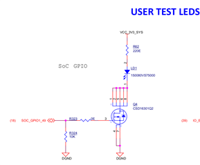
In the SDK by default, the LED is defined and connected to GPIO1_49. See below for the schematic connection and the device tree node. This should be consistent with both the U-Boot and Linux device trees.
/{

leds {
		compatible = "gpio-leds";
		pinctrl-names = "default";
		pinctrl-0 = <&usr_led_pins_default>;

		led-0 {
			label = "am62-sk:green:heartbeat";
			gpios = <&main_gpio1 49 GPIO_ACTIVE_HIGH>;
			linux,default-trigger = "heartbeat";
			function = LED_FUNCTION_HEARTBEAT;
			default-state = "off";
		};
	};
};

&main_pmx0 {
    usr_led_pins_default: usr-led-pins-default {
		pinctrl-single,pins = <
			AM62X_IOPAD(0x244, PIN_OUTPUT, 7) /* (C17/B15) MMC1_SDWP.GPIO1_49 */
		>;
	};
};
This LED is the 'heartbeat LED' which mimics the pattern of a beating heart. At U-Boot prompt, the LED is off by default, so we can enable the LED commands to use them at the prompt.
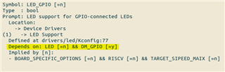
Notice how the device tree node contains 'compatible = "gpio-leds"; which means a normal GPIO driver will not apply here, rather a specific driver for GPIO-based LEDs is needed. We'll have to update the config file to include this.
The new config should include CONFIG_LED_GPIO=y and all of its dependencies (CONFIG_LED=y & CONFIG_DM_GPIO=y).
Use the SDK documentation for updating the config files and rebuild the images: https://software-dl.ti.com/processor-sdk-linux/esd/AM62X/09_02_01_10/exports/docs/linux/Foundational_Components/U-Boot/UG-General-Info.html#build-u-boot
U-Boot SPL 2023.04-dirty (Aug 09 2024 - 16:10:17 -0500)
SYSFW ABI: 3.1 (firmware rev 0x0009 '9.2.7--v09.02.07 (Kool Koala)')
SPL initial stack usage: 13408 bytes
Trying to boot from MMC2
Authentication passed
Authentication passed
Authentication passed
Authentication passed
Authentication passed
Starting ATF on ARM64 core...

NOTICE:  BL31: v2.10.0(release):v2.10.0-367-g00f1ec6b87-dirty
NOTICE:  BL31: Built : 16:09:05, Feb  9 2024

U-Boot SPL 2023.04-dirty (Aug 09 2024 - 16:10:26 -0500)
SYSFW ABI: 3.1 (firmware rev 0x0009 '9.2.7--v09.02.07 (Kool Koala)')
SPL initial stack usage: 1856 bytes
Trying to boot from MMC2
Authentication passed
Authentication passed


U-Boot 2023.04-dirty (Aug 09 2024 - 16:10:26 -0500)

SoC:   AM62X SR1.0 HS-FS
Model: Texas Instruments AM625 SK
EEPROM not available at 80, trying to read at 81
Board: AM62B-SKEVM-P1 rev A
DRAM:  2 GiB
Core:  74 devices, 34 uclasses, devicetree: separate
MMC:   mmc@fa10000: 0, mmc@fa00000: 1
Loading Environment from nowhere... OK
In:    serial
Out:   serial
Err:   serial
Net:   eth0: ethernet@8000000port@1
Hit any key to stop autoboot:  0
=>
=> led
led - manage LEDs

Usage:
led <led_label> on|off|toggle   Change LED state
led <led_label> Get LED state
led list                show a list of LEDs
=> led list
am62-sk:green:heartbeat
Change the state using on, off, & toggle.
=> led am62-sk:green:heartbeat on
=> led am62-sk:green:heartbeat off
=> led am62-sk:green:heartbeat toggle