This thread has been locked.

If you have a related question, please click the "Ask a related question" button in the top right corner. The newly created question will be automatically linked to this question.

AM6422: Issue with Enet Lwip TCP Server Example on ICSSG on TMDS64EVM

Part Number: AM6422
Other Parts Discussed in Thread: SYSCONFIG

Tool/software:

Hello 

I am using the AM64x MCU+ SDK (version 09.02.01) to implement the ICSSG LWIP TCP ECHO SERVER and facing multiple issues that appear to be discrepancies between the actual behavior and the SDK documentation. These issues persist across both static and dynamic IP configurations.

SDK Version: 09.02.01
ICSSG LWIP TCP ECHO SERVER

Core Issues
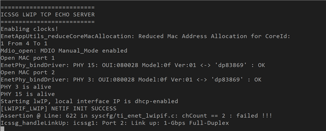
1. Assertion Failure in Both Configurations: Regardless of using static or DHCP IP configuration, I encounter an assertion error:
```
Assertion @ Line: 111 in /nightlybuilds/mcupsdk_internal/jenkins/mcu_plus_sdk_am64x_09_02_01_05/source/networking/enet/core/src/core/enet_queue.c: node != NULL
```

2. Documentation vs. Actual Behavior:
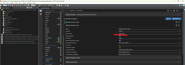
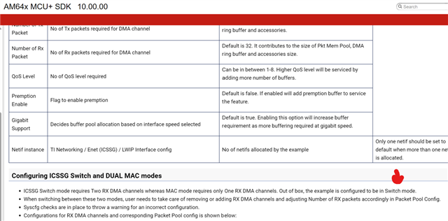
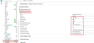
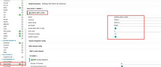
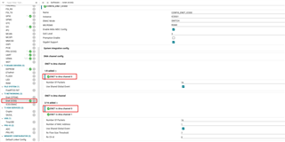
- The example code documentation states that out-of-the-box, the code should operate in "Switch mode," yet the Sysconfig indicates it's set to "Dual MAC mode."
- The log outputs from the example do not match the expected outputs as per the SDK documentation, particularly concerning network initialization and IP address assignment.

3. Difficulty Switching from DHCP to Static IP:
- The documentation instructs to disable DHCP and AUTOIP by removing `dhcp_start` and `autoip_start` calls. However, I am unable to locate these calls in the codebase, making it impossible to follow the prescribed steps for setting up a static IP.

1. How can I resolve the assertion error that occurs in both the static and dynamic IP configurations? Are there known bugs or patches for this issue?
2. Can you clarify the operational mode discrepancy? Why does the Sysconfig indicate "Dual MAC mode" when the documentation states "Switch mode" should be default?
3. Where exactly should I look to find and remove the `dhcp_start` and `autoip_start` calls within the ICSSG LWIP TCP ECHO SERVER example or related files in the SDK?
4. Are there additional steps or corrections in the documentation regarding setting up a static IP that I should be aware of?

  • Hi ,

    Thanks for your query.

    ICSSG LWIP TCP ECHO SERVER

    you are talking about this example ? AM64x MCU+ SDK: Enet Lwip TCP Server Example on ICSSG (ti.com)

    ICSSG LWIP TCP ECHO SERVER and facing multiple issues

    This observation is with out of box example on AM64x-HSFS-EVM ?  or after making some code changes ?

    mcu_plus_sdk_am64x_09_02_01_05/source/networking/enet/core/src/core/enet_queue.c

    And this file exist in installed location ?

    SDK Version: 09.02.01

    Can you quickly check with latest MCU SDK release ? 

    the code should operate in "Switch mode," yet the Sysconfig indicates it's set to "Dual MAC

    Please share the screenshot of this ?

    Regards

    Ashwani

  • Now I am using the latest SDK  v10

    Out of the box the EMAC mode is set to dual mac


    Also 


    I will check run tests on the latest sdk and let you know

  • Hi ,

    I think you are confusing with DUAL MAC and Switch mode.

    Please refer Configuring ICSSG DUAL MAC with two MAC ports section of AM64x MCU+ SDK: Enet Layer 2 ICSSG Example (ti.com)

    Also provide the reply for above pending questions (in my last reply).

    Regards

    Ashwani

  • Yes

    This observation is with out of box example on AM64x-HSFS-EVM ?  or after making some code changes ?

    Even without the code changes i.e out of the box

    And this file exist in installed location ?

    This file doesnt exist

    Can you quickly check with latest MCU SDK release ? 

    The latest sdk doesnt have this problem

    I think you are confusing with DUAL MAC and Switch mode.

    This might be a silly question but if the example should run as switch out of the box should the emac mode be set to DUAL_MAC? 

  • I am trying to build a modbus tcp server with the mac in switch mode. What should be the sequence of examples that I should try out so that I understand the basics of the enet driver as well as the lwip stack.

    Also I am fairly new to networking. I would love to understand the difference between the following examples

    >examples/networking/lwip/enet_lwip_icssg

    >examples/networking/lwip/enet_icssg_tcpserver

  • Thanks Atharv,

    I am trying to build a modbus tcp server with the mac in switch mode

    Can you help me with the end use case ?

    You want to run modbus on ICSSG dual mac (single port on ICSSG1) ?

    or

    You want to run modbus on ICSSG switch (ICSSG1 in switch mode) ?

    Please refer below documentation for respective examples.

    examples/networking/lwip/enet_lwip_icssg

    AM64x MCU+ SDK: Enet Lwip ICSSG Example (ti.com)

    examples/networking/lwip/enet_icssg_tcpserver

    AM64x MCU+ SDK: Enet Lwip TCP Server Example on ICSSG (ti.com)

    Regards

    Ashwani

  • Can you help me with the end use case ?

    I want to create a TCP server that can handle Modbus packets with the ICSSGI in switch mode. 

    I was able to handle modbus packets with this example. The only problem being that the example is in dual mac out of the box.

    AM64x MCU+ SDK: Enet Lwip TCP Server Example on ICSSG (ti.com)

    Since I need a tcp server but with icssgi in switch mode I attempt to modify the sysconfig of this example by following steps given in 
    https://software-dl.ti.com/mcu-plus-sdk/esd/AM64X/10_00_00_20/exports/docs/api_guide_am64x/EXAMPLES_ENET_LAYER2_ICSSG.html#autotoc_md1316 and 
    https://software-dl.ti.com/mcu-plus-sdk/esd/AM64X/10_00_00_20/exports/docs/api_guide_am64x/EXAMPLES_ENET_LWIP_ICSSG.html

    This was the final sysconfig after the changes 

    /**
     * These arguments were used when this file was generated. They will be automatically applied on subsequent loads
     * via the GUI or CLI. Run CLI with '--help' for additional information on how to override these arguments.
     * @cliArgs --device "AM64x" --package "ALV" --part "Default" --context "r5fss0-0" --product "MCU_PLUS_SDK_AM64x@10.00.00"
     * @versions {"tool":"1.20.0+3587"}
     */
    
    /**
     * Import the modules used in this configuration.
     */
    const eeprom     = scripting.addModule("/board/eeprom/eeprom", {}, false);
    const eeprom1    = eeprom.addInstance();
    const gpio       = scripting.addModule("/drivers/gpio/gpio", {}, false);
    const gpio1      = gpio.addInstance();
    const i2c        = scripting.addModule("/drivers/i2c/i2c", {}, false);
    const i2c1       = i2c.addInstance();
    const i2c2       = i2c.addInstance();
    const pruicss    = scripting.addModule("/drivers/pruicss/pruicss", {}, false);
    const pruicss1   = pruicss.addInstance();
    const debug_log  = scripting.addModule("/kernel/dpl/debug_log");
    const dpl_cfg    = scripting.addModule("/kernel/dpl/dpl_cfg");
    const mpu_armv7  = scripting.addModule("/kernel/dpl/mpu_armv7", {}, false);
    const mpu_armv71 = mpu_armv7.addInstance();
    const mpu_armv72 = mpu_armv7.addInstance();
    const mpu_armv73 = mpu_armv7.addInstance();
    const mpu_armv74 = mpu_armv7.addInstance();
    const mpu_armv75 = mpu_armv7.addInstance();
    const mpu_armv76 = mpu_armv7.addInstance();
    const mpu_armv77 = mpu_armv7.addInstance();
    const enet_icss  = scripting.addModule("/networking/enet_icss/enet_icss", {}, false);
    const enet_icss1 = enet_icss.addInstance();
    
    /**
     * Write custom configuration values to the imported modules.
     */
    eeprom1.$name = "CONFIG_EEPROM0";
    
    gpio1.$name                    = "CONFIG_GPIO0";
    gpio1.pinDir                   = "OUTPUT";
    gpio1.useMcuDomainPeripherals  = true;
    gpio1.MCU_GPIO.$assign         = "MCU_GPIO0";
    gpio1.MCU_GPIO.gpioPin.$assign = "MCU_SPI1_CS0";
    
    i2c1.$name               = "CONFIG_I2C0";
    eeprom1.peripheralDriver = i2c1;
    i2c1.I2C.$assign         = "I2C0";
    i2c1.I2C.SCL.$assign     = "I2C0_SCL";
    i2c1.I2C.SDA.$assign     = "I2C0_SDA";
    i2c1.I2C_child.$name     = "drivers_i2c_v0_i2c_v0_template1";
    
    i2c2.$name           = "CONFIG_I2C1";
    i2c2.I2C.$assign     = "I2C1";
    i2c2.I2C.SCL.$assign = "I2C1_SCL";
    i2c2.I2C.SDA.$assign = "I2C1_SDA";
    i2c2.I2C_child.$name = "drivers_i2c_v0_i2c_v0_template2";
    
    debug_log.enableUartLog = true;
    debug_log.enableCssLog  = false;
    debug_log.uartLog.$name = "CONFIG_UART0";
    
    const uart_v0_template  = scripting.addModule("/drivers/uart/v0/uart_v0_template", {}, false);
    const uart_v0_template1 = uart_v0_template.addInstance({}, false);
    uart_v0_template1.$name = "drivers_uart_v0_uart_v0_template0";
    debug_log.uartLog.child = uart_v0_template1;
    
    mpu_armv71.$name             = "CONFIG_MPU_REGION0";
    mpu_armv71.size              = 31;
    mpu_armv71.attributes        = "Device";
    mpu_armv71.accessPermissions = "Supervisor RD+WR, User RD";
    mpu_armv71.allowExecute      = false;
    
    mpu_armv72.$name             = "CONFIG_MPU_REGION1";
    mpu_armv72.size              = 15;
    mpu_armv72.accessPermissions = "Supervisor RD+WR, User RD";
    
    mpu_armv73.$name             = "CONFIG_MPU_REGION2";
    mpu_armv73.baseAddr          = 0x41010000;
    mpu_armv73.size              = 15;
    mpu_armv73.accessPermissions = "Supervisor RD+WR, User RD";
    
    mpu_armv74.$name             = "CONFIG_MPU_REGION3";
    mpu_armv74.accessPermissions = "Supervisor RD+WR, User RD";
    mpu_armv74.baseAddr          = 0x70000000;
    mpu_armv74.size              = 23;
    
    mpu_armv75.$name             = "CONFIG_MPU_REGION4";
    mpu_armv75.accessPermissions = "Supervisor RD+WR, User RD";
    mpu_armv75.baseAddr          = 0x80000000;
    mpu_armv75.size              = 31;
    
    mpu_armv76.$name             = "CONFIG_MPU_REGION5";
    mpu_armv76.accessPermissions = "Supervisor RD+WR, User RD";
    mpu_armv76.baseAddr          = 0xA5000000;
    mpu_armv76.size              = 23;
    mpu_armv76.attributes        = "NonCached";
    
    mpu_armv77.$name    = "CONFIG_MPU_REGION6";
    mpu_armv77.size     = 27;
    mpu_armv77.baseAddr = 0x60000000;
    
    enet_icss1.$name                        = "CONFIG_ENET_ICSS0";
    enet_icss1.phyToMacInterfaceMode        = "RGMII";
    enet_icss1.mdioMode                     = "MDIO_MODE_MANUAL";
    enet_icss1.PktInfoOnlyEnable            = true;
    enet_icss1.QoS                          = 3;
    enet_icss1.LargePoolPktCount            = 64;
    enet_icss1.txDmaChannel[0].$name        = "ENET_DMA_TX_CH0";
    enet_icss1.netifInstance.create(1);
    enet_icss1.netifInstance[0].$name       = "NETIF_INST_ID0";
    enet_icss1.PRU_ICSSG1_RGMII1.$assign    = "PRU_ICSSG1_RGMII1";
    enet_icss1.rxDmaChannel[0].$name        = "ENET_DMA_RX_CH0";
    enet_icss1.rxDmaChannel[1].$name        = "ENET_DMA_RX_CH1";
    enet_icss1.rxDmaChannel[1].macAddrCount = 0;
    enet_icss1.rxDmaChannel[1].chIdx        = 1;
    
    enet_icss1.icss                          = pruicss1;
    pruicss1.$name                           = "CONFIG_PRU_ICSS1";
    pruicss1.AdditionalICSSSettings[0].$name = "CONFIG_PRU_ICSS_IO0";
    pruicss1.intcMapping.create(2);
    pruicss1.intcMapping[0].$name            = "CONFIG_ICSS1_INTC_MAPPING0";
    pruicss1.intcMapping[0].event            = "41";
    pruicss1.intcMapping[0].channel          = "7";
    pruicss1.intcMapping[0].host             = "8";
    pruicss1.intcMapping[1].$name            = "CONFIG_ICSS1_INTC_MAPPING1";
    pruicss1.intcMapping[1].channel          = "7";
    pruicss1.intcMapping[1].host             = "8";
    pruicss1.intcMapping[1].event            = "53";
    
    const udma         = scripting.addModule("/drivers/udma/udma", {}, false);
    const udma1        = udma.addInstance({}, false);
    enet_icss1.udmaDrv = udma1;
    
    /**
     * Pinmux solution for unlocked pins/peripherals. This ensures that minor changes to the automatic solver in a future
     * version of the tool will not impact the pinmux you originally saw.  These lines can be completely deleted in order to
     * re-solve from scratch.
     */
    debug_log.uartLog.UART.$suggestSolution                  = "USART0";
    debug_log.uartLog.UART.RXD.$suggestSolution              = "UART0_RXD";
    debug_log.uartLog.UART.TXD.$suggestSolution              = "UART0_TXD";
    enet_icss1.PRU_ICSSG1_MDIO.$suggestSolution              = "PRU_ICSSG1_MDIO0";
    enet_icss1.PRU_ICSSG1_MDIO.MDC.$suggestSolution          = "PRG1_MDIO0_MDC";
    enet_icss1.PRU_ICSSG1_MDIO.MDIO.$suggestSolution         = "PRG1_MDIO0_MDIO";
    enet_icss1.PRU_ICSSG1_IEP.$suggestSolution               = "PRU_ICSSG1_IEP0";
    enet_icss1.PRU_ICSSG1_IEP.EDC_LATCH_IN0.$suggestSolution = "PRG1_PRU0_GPO18";
    enet_icss1.PRU_ICSSG1_IEP.EDC_SYNC_OUT0.$suggestSolution = "PRG1_PRU0_GPO19";
    enet_icss1.PRU_ICSSG1_RGMII1.RD0.$suggestSolution        = "PRG1_PRU0_GPO0";
    enet_icss1.PRU_ICSSG1_RGMII1.RD1.$suggestSolution        = "PRG1_PRU0_GPO1";
    enet_icss1.PRU_ICSSG1_RGMII1.RD2.$suggestSolution        = "PRG1_PRU0_GPO2";
    enet_icss1.PRU_ICSSG1_RGMII1.RD3.$suggestSolution        = "PRG1_PRU0_GPO3";
    enet_icss1.PRU_ICSSG1_RGMII1.RXC.$suggestSolution        = "PRG1_PRU0_GPO6";
    enet_icss1.PRU_ICSSG1_RGMII1.RX_CTL.$suggestSolution     = "PRG1_PRU0_GPO4";
    enet_icss1.PRU_ICSSG1_RGMII1.TD0.$suggestSolution        = "PRG1_PRU0_GPO11";
    enet_icss1.PRU_ICSSG1_RGMII1.TD1.$suggestSolution        = "PRG1_PRU0_GPO12";
    enet_icss1.PRU_ICSSG1_RGMII1.TD2.$suggestSolution        = "PRG1_PRU0_GPO13";
    enet_icss1.PRU_ICSSG1_RGMII1.TD3.$suggestSolution        = "PRG1_PRU0_GPO14";
    enet_icss1.PRU_ICSSG1_RGMII1.TXC.$suggestSolution        = "PRG1_PRU0_GPO16";
    enet_icss1.PRU_ICSSG1_RGMII1.TX_CTL.$suggestSolution     = "PRG1_PRU0_GPO15";
    enet_icss1.PRU_ICSSG1_RGMII2.$suggestSolution            = "PRU_ICSSG1_RGMII2";
    enet_icss1.PRU_ICSSG1_RGMII2.RD0.$suggestSolution        = "PRG1_PRU1_GPO0";
    enet_icss1.PRU_ICSSG1_RGMII2.RD1.$suggestSolution        = "PRG1_PRU1_GPO1";
    enet_icss1.PRU_ICSSG1_RGMII2.RD2.$suggestSolution        = "PRG1_PRU1_GPO2";
    enet_icss1.PRU_ICSSG1_RGMII2.RD3.$suggestSolution        = "PRG1_PRU1_GPO3";
    enet_icss1.PRU_ICSSG1_RGMII2.RXC.$suggestSolution        = "PRG1_PRU1_GPO6";
    enet_icss1.PRU_ICSSG1_RGMII2.RX_CTL.$suggestSolution     = "PRG1_PRU1_GPO4";
    enet_icss1.PRU_ICSSG1_RGMII2.TD0.$suggestSolution        = "PRG1_PRU1_GPO11";
    enet_icss1.PRU_ICSSG1_RGMII2.TD1.$suggestSolution        = "PRG1_PRU1_GPO12";
    enet_icss1.PRU_ICSSG1_RGMII2.TD2.$suggestSolution        = "PRG1_PRU1_GPO13";
    enet_icss1.PRU_ICSSG1_RGMII2.TD3.$suggestSolution        = "PRG1_PRU1_GPO14";
    enet_icss1.PRU_ICSSG1_RGMII2.TXC.$suggestSolution        = "PRG1_PRU1_GPO16";
    enet_icss1.PRU_ICSSG1_RGMII2.TX_CTL.$suggestSolution     = "PRG1_PRU1_GPO15";
    

    But upon running i get 

  • Hi ,

    It shows Rx/Tx channels are not properly configured.

    I am assuming you have removed CONFIG_ENET_ICSS1 from below screenshot

    Change DUAL MAC setting to SWITCH mode as below

    Rx and Tx DMA channels

    Single NETIF for 2-Rx and 1-Tx channels

    Let me know if you are still facing issue?

    Regards

    Ashwani

  • Hi Ashwani,

    Thanks a lot for your prompt response and guidance!

    The Rx DMA used for the Netif had to be set to [0,1].