Part Number: TDA4VM
Tool/software:
Hi,
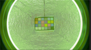
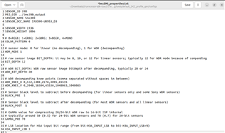
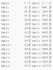
I am currently using TDA4VM and otobrite IMX390 camera to do CFAI+WDR in ISP Tuning. The SDK version I am using is 9.2.0.5, and the DCC Tool is using version 3.0.
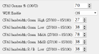
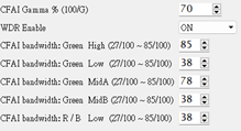
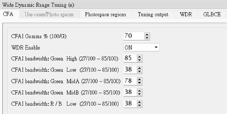
From the DCC tool operation manual, I know that increasing CFAI bandwidth Green High and CFAI bandwidth Green Low provides a clearer output image with more noise and artifacts.
Reducing the CFAI bandwidth Green MidA and MidB will result in less noise, fewer artifacts and lower resolution.
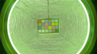
When I set these values to their minimum values, I can't see any difference in noise or artifacts from the original image, I can only see that my image becomes very yellow.
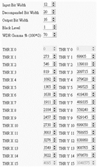
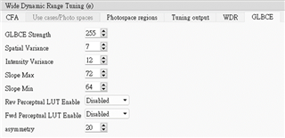
I lowered the GLBCE Strength value, but I can't see any weakening in the brightness and contrast of the image.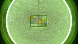
I tried to change the parameters mentioned in the operation manual that can affect the image effect, but I couldn't observe any changes in my image.
I would like you to help me explain or tell me where the problem is. Thank you.