This thread has been locked.

If you have a related question, please click the "Ask a related question" button in the top right corner. The newly created question will be automatically linked to this question.

AM625: Interrupt and pin setting for external Touch IC

Part Number: AM625
Other Parts Discussed in Thread: PCA9554, PCA9555

Tool/software:

Hell TI Expert

We are porting gt911 touch on AM6254 ALW SDK 9.0.

May you guide device tree setting?

Do we have to define Pin muxing for MCU_GPIO0_10 and MCU_GPIO0_9?

Please kindly guide. Thanks.

We try below, but it does not work.

goodix_ts@5d {
compatible = "goodix,gt9xx";
reg = <0x5d>;
interrupt-parent = <&mcugpio0>;
//interrupts = <17 0x2008>;
//vdd_ana-supply = <&pm8226_l19>;
//vcc_i2c-supply = <&pm8226_lvs1>;
goodix,rst-gpio = <&mcugpio0 10 GPIO_ACTIVE_HIGH>;
goodix,irq-gpio = <&mcugpio0 9 GPIO_ACTIVE_LOW>;

}

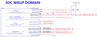
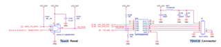
Our connection interface:

  • 1, how to set/use it MCU_GPIO0_10 as reset pin

    2, how to set/use MCU_GPIO0_9 as interrupt pion and where could i find out its interrupt parent?

  • Hi Paul,

    Can you explain why the compatible field has xx (compatible = "goodix,gt9xx";)? Are you using a custom driver? TI is unable to provide support for custom Linux drivers and applications.

    Looking through the device tree documentation, the compatible field is compatible = "goodix,gt911";

    Can you share the MCU GPIO pinmux and reference node used by this?

    Best Regards,

    Anshu

  • Hello Anshu, 

    "goodix,gt9xx" is a customized version of  "goodix,gt911". 

    I just found a reference dts in SDK 9.0 "k3-am654-evm-oldi-lcd1evm.dtso" but it is just another diff version of external touch IC and it connects to diff pins of AM62x.

    &main_i2c1 {
    #address-cells = <1>;
    #size-cells = <0>;

    gt928: touchscreen@14 {
    status = "okay";
    compatible = "goodix,gt928";
    reg = <0x14>;

    interrupt-parent = <&pca9554>;
    interrupts = <3 IRQ_TYPE_EDGE_FALLING>;
    touchscreen-size-x = <1280>;
    touchscreen-size-y = <800>;

    reset-gpios = <&pca9555 9 GPIO_ACTIVE_HIGH>;
    irq-gpios = <&pca9554 3 GPIO_ACTIVE_HIGH>;
    };
    };

    Here for AM62x SoC as in our HW schematic, we want to use 

    1, MCU_GPIO0_10 as reset pin

    2, MCU_GPIO0_9 as interrupt pin

    "Can you share the MCU GPIO pinmux and reference node used by this?"

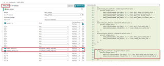
    We try to config the pimux as below, but we don't know how to use and fill in the driver node:

    May you help for this dts?

    goodix_ts@5d {
    compatible = "goodix,gt9xx";
    reg = <0x5d>;
    interrupt-parent = <?>;   
    goodix,rst-gpio = <?>;    //MCU_GPIO0_10, Pin C5
    goodix,irq-gpio = <?>;    //MCU_GPIO0_9, Pin B4

    }

  • Hi Paul,

    You are calling "&mcugpio0" in the IRQ and reset parameters. Where is &mcugpio0 defined? Can you try &mcu_gpio0?

  • hello Anshu, 

    yes, it should be mcu_gpio0, we are trying.

    1) We use MCU_GPIO0_9 as interrupt pin, what its interrupt-parent?

    2) Could we use them directly (e.g < &mcu_gpio0 9 GPIO_ACTIVE_LOW>) ?

    or we need to do use their pinmuxing?

    < &mcugpio0_mcu_gpio_9_irq_pins_default 9 GPIO_ACTIVE_LOW>

    < &mcugpio0_mcu_gpio_10_reset_pins_default 9 GPIO_ACTIVE_LOW>

    &mcu_pmx0 {

    mcugpio0_mcu_gpio_9_irq_pins_default: mcugpio0-default-pins {
    pinctrl-single,pins = <
    AM62X_MCU_IOPAD(0x0024, PIN_INPUT_PULLDOWN, 7) /* (B4) WKUP_UART0_RXD.MCU_GPIO0_9 */
    >;
    };

    mcugpio0_mcu_gpio_10_reset_pins_default: mcugpio0-default-pins {
    pinctrl-single,pins = <
    AM62X_MCU_IOPAD(0x0028, PIN_OUTPUT_PULLDOWN, 7) /* (C5) WKUP_UART0_TXD.MCU_GPIO0_10 */
    >;
    };

    };

  • Hi Paul,

    Here are the device tree bindings: https://git.ti.com/cgit/ti-linux-kernel/ti-linux-kernel/tree/Documentation/devicetree/bindings/iio/light/ti,opt3001.yaml?h=ti-linux-6.1.y

    The interrupt parent should be &mcu_gpio0. You shouldn't need the pinmuxing in the 'interrupts' definition.

    Best Regards,

    Anshu

  • Hello Anshu, 

    May you check our irq and reset pin setting? It still does not work.

    Could you guide how to verify this irq  ("mcu_gpio0 9") and reset pin ("mcu_gpio0 10")?

    touchscreen@5d {
    compatible = "goodix,gt911";
    reg = <0x5d>;
    //pinctrl-names = "default";
    //pinctrl-0 = <&touchscreen_pins_default>;
    interrupt-parent = <&mcu_gpio0>;
    interrupts = <9 IRQ_TYPE_EDGE_RISING>;
    irq-gpios = <&mcu_gpio0 9 GPIO_ACTIVE_LOW>;
    reset-gpios = <&mcu_gpio0 10 GPIO_ACTIVE_LOW>;

    }

  • FYI, We also try   interrupts = <9 IRQ_TYPE_EDGE_FALLING>;

    "mcu_gpio0 9" we use it as irq, do we need to set direction (INPUT) of this gpio?

  • Hi Paul,

    May you check our irq and reset pin setting?

    Nothing seems wrong.

    do we need to set direction (INPUT) of this gpio?

    Yes it needs to be input.


    To debug further, you can check the output of 'cat /proc/interrupts' & also decompile the dtb to see if there any issues how the node was compiled.

    Thanks,

    Anshu

  • Hello Anshu

    Because reset pin does not work, we want to control (LOW or HIGH) "mcu_gpio0 10"  (reset pin) mannually but I could not.

    May you guide?

    root@am62xx-evm:~# cat /sys/kernel/debug/gpio
    gpiochip2: GPIOs 344-395, parent: platform/601000.gpio, 601000.gpio:

    gpiochip1: GPIOs 396-487, parent: platform/600000.gpio, 600000.gpio:
    gpio-427 ( |tlv71033 ) out lo

    gpiochip0: GPIOs 488-511, parent: platform/4201000.gpio, 4201000.gpio:

    ==================

    gpiochip0: GPIOs 488

    488 + 10 = 498

    ==================

    root@am62xx-evm:~# echo 498 > /sys/class/gpio/export
    root@am62xx-evm:~# echo out > /sys/class/gpio/gpio498/direction
    root@am62xx-evm:~# echo 0 > /sys/class/gpio/gpio498/value      /* On Scope: Signal is Not LOW */
    root@am62xx-evm:~# echo 1 > /sys/class/gpio/gpio498/value      /* On Scope: Signal is Not HIGH */

    root@am62xx-evm:~# cat /sys/kernel/debug/gpio
    gpiochip2: GPIOs 344-395, parent: platform/601000.gpio, 601000.gpio:

    gpiochip1: GPIOs 396-487, parent: platform/600000.gpio, 600000.gpio:
    gpio-427 ( |tlv71033 ) out lo

    gpiochip0: GPIOs 488-511, parent: platform/4201000.gpio, 4201000.gpio:
    gpio-498 ( |sysfs ) out lo

  • Hi Paul,

    Just as a check, are you able to toggle the GPIO normally without the device connected?

    Thanks,

    Anshu

  • Hello Anshu, 

    We removed the device and we are also not able to see signal HIGH or LOW. (we also try with below gpioset).

    root@am62xx-evm:~# ls -l /sys/class/gpio
    total 0
    --w------- 1 root root 4096 Apr 28 2022 export
    lrwxrwxrwx 1 root root 0 Apr 28 2022 gpiochip344 -> ../../devices/platform/bus@f0000/601000.gpio/gpio/gpiochip344
    lrwxrwxrwx 1 root root 0 Apr 28 2022 gpiochip396 -> ../../devices/platform/bus@f0000/600000.gpio/gpio/gpiochip396
    lrwxrwxrwx 1 root root 0 Apr 28 2022 gpiochip488 -> ../../devices/platform/bus@f0000/bus@f0000:bus@4000000/4201000.gpio/gpio/gpiochip488 = gpiochip0
    --w------- 1 root root 4096 Apr 28 2022 unexport


    root@am62xx-evm:~# gpiodetect
    gpiochip0 [4201000.gpio] (24 lines)
    gpiochip1 [600000.gpio] (92 lines)
    gpiochip2 [601000.gpio] (52 lines)

    root@am62xx-evm:~# gpioset 0 10=0
    root@am62xx-evm:~# gpioset 0 10=1
    root@am62xx-evm:~# gpioinfo
    gpiochip0 - 24 lines:
    line 0: unnamed unused input active-high
    line 1: unnamed unused input active-high
    line 2: unnamed unused input active-high
    line 3: unnamed unused input active-high
    line 4: unnamed unused input active-high
    line 5: unnamed unused input active-high
    line 6: unnamed unused input active-high
    line 7: unnamed unused input active-high
    line 8: unnamed unused input active-high
    line 9: unnamed unused input active-high
    line 10: unnamed unused output active-high
    line 11: unnamed unused input active-high
    line 12: unnamed unused input active-high

  • FYI, Our current dts setting ( with the muxing or not, the result is the same).

    &mcu_pmx0 {
    touchscreen_pins_default: touchscreen-default-pins {
    pinctrl-single,pins = <
    AM62X_MCU_IOPAD(0x0024, PIN_INPUT, 0) /* (B4) WKUP_UART0_RXD */ /* for interrupt pin*/
    AM62X_MCU_IOPAD(0x0028, PIN_OUTPUT, 0) /* (C5) WKUP_UART0_TXD */  /* for reset pin*/
    >;
    };
    };

  • Hello Anshu

    May you help?

    We face difficulty to control MCU_GPIO0_10 and MCU_GPIO0_9 to low or high.