This thread has been locked.

If you have a related question, please click the "Ask a related question" button in the top right corner. The newly created question will be automatically linked to this question.

TMS320C6748: PCB Layoout Guidline

Part Number: TMS320C6748

Tool/software:

Hi C6748 Champ !

My customer uses TMS320C6748EZCEA3  part for their next model.

HW engineer would like to check impedance related. He found the following descriptions. 

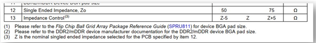
His understanding was that the impedance (Z0) could be 50 to 75 ohm design and 45 to 55 ohm with +/- 5 ohm for a 50 ohm design.
Then, when designing the PCB, please confirm whether it is possible to calculate 50 ohm for the layer mounting the IC and 47 ohm for the Data Line Layer and design the PCB.
I would like a quick and accurate confirmation as I will pass it to the PCB manufacturer.

Thanks

Best Regards, 

Jack 

  • I discussed this topic with our DDR expert, and he confirmed the PCB trace impedance is allowed to be anywhere in the range of 50 Ohms to 75 Ohms with a maximum impedance tolerance of +/-5 Ohms from the target impedance. He also said most customers design their PCBs with target trace impedance that is closer to lower end of the 50 Ohm to 75 Ohm range, so suggested you do the same.

    Regards,
    Paul