Part Number: AM3352
Tool/software:
Hello Support-Team,
how could we get the right values for gpio numbers in kernel if we want to use gpio3_9 and gpio3_10 as reset and irq.
We have in DTS <105> and <106>
&spi0 {

            status = "okay";

            pinctrl-names = "default";

            pinctrl-0 = <&spi0_pins>;

            ti,pindir-d0-out-d1-in = <1>;


            ksz8895: ksz8895@0 {

                compatible = "micrel,ksz8895";

                spi-max-frequency = <12000000>;

                spi-cpha;

                spi-cpol;

                phy-mode = "mii";

                reg = <0>;  /* Chip select 0 */


                ksz8895,gpio_reset = <106>; /* GPIO_TO_PIN(3,10) */

                ksz8895,gpio_irq = <105>; /* GPIO_TO_PIN(3,9) */

                ports {

                        #address-cells = <1>;

                        #size-cells = <0>;

                        port@0 {

                            reg = <0>;

                            label = "lan1";

                        };

                        port@1 {

                            reg = <1>;

                            label = "lan2";

                        };

                        port@2 {

                            reg = <2>;

                            label = "lan3";

                        };

                        port@3 {

                            reg = <3>;

                            label = "lan4";

                        };

                        port@4 {

                            reg = <4>;

                            label = "cpu";

                            ethernet = <&mac>;

                            phy-mode = "mii";

                            fixed-link {

                                speed = <100>;

                                full-duplex;

                            };

                        };

                    };

            };

        };
But is mapped to gpio0.
Like you can see here:
root@beagletest:~# cat /proc/interrupts
CPU0
16: 4398 INTC 68 Level clockevent
17: 0 INTC 96 Level 44e07000.gpio
23: 0 INTC 98 Level 4804c000.gpio
24: 0 INTC 4 Level 48080000.elm
25: 309 INTC 30 Level 4819c000.i2c
26: 0 INTC 32 Level 481ac000.gpio
27: 0 INTC 62 Level 481ae000.gpio
28: 0 INTC 111 Level 48310000.rng
29: 0 INTC 41 Level 4a100000.ethernet
30: 19 INTC 42 Level 4a100000.ethernet
31: 25 INTC 43 Level 4a100000.ethernet
32: 538 INTC 12 Level 49000000.dma_ccint
33: 0 INTC 14 Level 49000000.dma_ccerrint
34: 0 INTC 3 Level arm-pmu
35: 503 INTC 72 Level 44e09000.serial
36: 516 INTC 70 Level 44e0b000.i2c
37: 0 INTC 65 Level 48030000.spi
38: 0 44e07000.gpio 9 Edge ksz8895
39: 1970 INTC 64 Level mmc0
40: 0 44e07000.gpio 17 Edge 48060000.mmc cd
Err: 0
gpio0_target: target-module@7000 { /* 0x44e07000, ap 14 20.0 */
compatible = "ti,sysc-omap2", "ti,sysc";
reg = <0x7000 0x4>,
<0x7010 0x4>,
<0x7114 0x4>;
reg-names = "rev", "sysc", "syss";
ti,sysc-mask = <(SYSC_OMAP2_ENAWAKEUP |
SYSC_OMAP2_SOFTRESET |
SYSC_OMAP2_AUTOIDLE)>;
ti,sysc-sidle = <SYSC_IDLE_FORCE>,
<SYSC_IDLE_NO>,
<SYSC_IDLE_SMART>,
<SYSC_IDLE_SMART_WKUP>;
ti,syss-mask = <1>;
/* Domains (P, C): wkup_pwrdm, l4_wkup_clkdm */
clocks = <&l4_wkup_clkctrl AM3_L4_WKUP_GPIO1_CLKCTRL 0>,
<&l4_wkup_clkctrl AM3_L4_WKUP_GPIO1_CLKCTRL 18>;
clock-names = "fck", "dbclk";
#address-cells = <1>;
#size-cells = <1>;
ranges = <0x0 0x7000 0x1000>;
gpio0: gpio@0 {
compatible = "ti,omap4-gpio";
gpio-ranges = <&am33xx_pinmux 0 82 8>,
<&am33xx_pinmux 8 52 4>,
<&am33xx_pinmux 12 94 4>,
<&am33xx_pinmux 16 71 2>,
<&am33xx_pinmux 18 135 1>,
<&am33xx_pinmux 19 108 2>,
<&am33xx_pinmux 21 73 1>,
<&am33xx_pinmux 22 8 2>,
<&am33xx_pinmux 26 10 2>,
<&am33xx_pinmux 28 74 1>,
<&am33xx_pinmux 29 81 1>,
<&am33xx_pinmux 30 28 2>;
gpio-controller;
#gpio-cells = <2>;
interrupt-controller;
#interrupt-cells = <2>;
reg = <0x0 0x1000>;
interrupts = <96>;
};
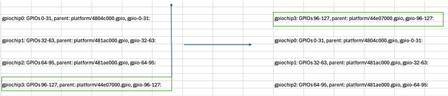
};Comparing kernel 5 and 6 we have discrepancy in cat /sys/kernel/debug/gpio.
|
Correct: GPIO3 is used with 481ae000 gpiochip0: GPIOs 0-31, parent: platform/44e07000.gpio, gpio-0-31: gpiochip1: GPIOs 32-63, parent: platform/4804c000.gpio, gpio-32-63: gpiochip2: GPIOs 64-95, parent: platform/481ac000.gpio, gpio-64-95: gpiochip3: GPIOs 96-127, parent: platform/481ae000.gpio, gpio-96-127: gpio-105 ( |ksz8895 irq ) in hi IRQ gpio-106 ( |ksz8895 reset ) out lo |
Wrong: GPIO0 is used with root@beagletest:~# cat /sys/kernel/debug/gpio gpiochip0: GPIOs 0-31, parent: platform/4804c000.gpio, gpio-0-31: gpiochip1: GPIOs 32-63, parent: platform/481ac000.gpio, gpio-32-63: gpiochip2: GPIOs 64-95, parent: platform/481ae000.gpio, gpio-64-95: gpiochip3: GPIOs 96-127, parent: platform/44e07000.gpio, gpio-96-127: gpio-105 ( |ksz8895 irq ) in lo IRQ gpio-106 ( |ksz8895 reset ) out lo gpio-113 ( |cd ) in lo IRQ ACTIVE LOW |
How to solve this? How to have the same order according to addresses like in kernel 5?