This thread has been locked.

If you have a related question, please click the "Ask a related question" button in the top right corner. The newly created question will be automatically linked to this question.

[FAQ] How to Setup IBV icECAT EtherCAT Master Stack on TI Processors?

Part Number: AM6442
Other Parts Discussed in Thread: LP-AM243, TMDS64EVM

Tool/software:

icECAT is a 3rd party EtherCAT Master stack developed by IBV.

To obtain the software stack for evaluation please send a request by selecting the "Send Request" button at the bottom of https://www.ibv-augsburg.de/en/products/icnet/ethercat-master/.

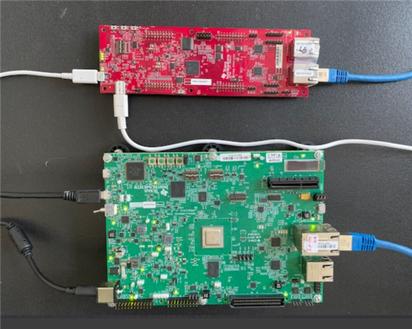
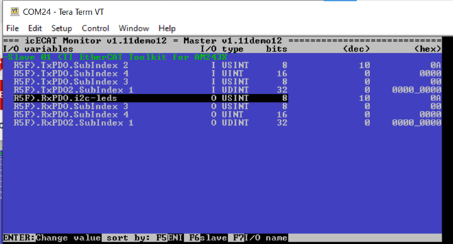
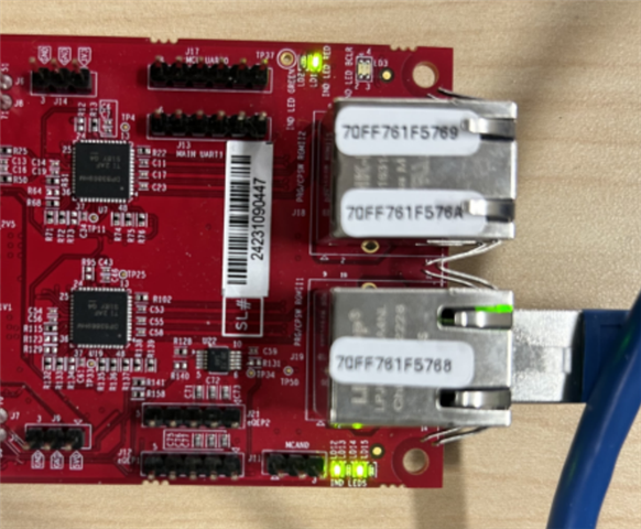
This FAQ describes steps to setup a sample icECAT EtherCAT Master application on AM64x EVM (TMDS64EVM) with a single LP-AM243 running an EtherCAT subdevice example.

  • Hardware Requirements/Setup

    1. EtherCAT MainDevice: TMDS64EVM

    2. EtherCAT SubDevice: LP-AM243

    3. Micro-SD card formatted to contain a FAT partition as the primary partition 

    4. A host PC for connecting the UART serial port from the TMDS64EVM

    5. Connect the devices as shown in the picture below. Use the top RJ45 Ethernet port on the 2-port connector of the TMDS64EVM.

  • Setting up EtherCAT SubDevice

    1. Download ind_comms_sdk_am243x_09_02_00_08

    2. Build the ethercat_slave_simple_demo_am243x-lp_r5fss0-0_freertos_ti-arm-clang example from examples\industrial_comms\ethercat_slave_demo\device_profiles\401_simple to generate an .appimage file

    3. Flash the appimage file to the LP-AM243 using the steps provided in https://software-dl.ti.com/mcu-plus-sdk/esd/AM243X/latest/exports/docs/api_guide_am243x/GETTING_STARTED_FLASH.html

    4. We recommend flashing using OSPI flash so that the example doesn't need to be loaded everytime the LP-AM243 is power-cycled

  • Setting up the EtherCAT MainDevice

    This FAQ is based on _ECATM_Getting_Started_TI_AM64x.pdf and try to summarize the steps to get an AM264x/AM243x EVM to work as EtherCAT MainDevice using IBV stack plus an AM243x LP as a SubDevice. For further details or how to work with other SubDevices please check _ECATM_Getting_Started_TI_AM64x.pdf

    1. Read the details provided in Chapter 2 of _ECATM_Getting_Started_TI_AM64x.pdf which should be included in your icECAT software package

    2. Download and patch the mcu_plus_sdk_am64x_09_02_00_50 - as explained in _ECATM_Getting_Started_TI_AM64x.pdf

    3. Rebuild the libraries 

    cd C:\ti\mcu_plus_sdk_am64x_09_02_00_50
    gmake -j4 -s libs-clean PROFILE=release
    gmake -j4 -s libs PROFILE=release
    

    4. Repeat for debug profile if needed

    5. TIP: More details on how to build and work with makefiles in MCU+SDK: AM243x MCU+ SDK: Using SDK with Makefiles (ti.com)

    6. For this FAQ we configure the icECAT Master example application (using "ecatm-sample-appl" in this example) to the following

    • SD card boot
    • ENI (EtherCAT Network Information) file loaded from SD card
    • Enable linked monitor
    • Disable IP network

    Note: Other configuration (ex: using CCS to build/run, use Static ENI file, using server etc) are explained in _ECATM_Getting_Started_TI_AM64x.pdf

    To do this ensure the following are configured in the icECAT software package

    ICNET\INSTALL\include\freertos_am64x_r5f_evm\ecatm_config_tgtsys.h
    
    #define COMPILE_ECATM_ENI_USE_FILE_IO  1  /* access ENI info via FILE I/O     */
    #undef  COMPILE_ECATM_ENI_USE_STATIC
    #define COMPILE_ECATM_ENI_USE_STATIC   0  /* static ENI information in source */
    
    /* enable server for EtherCAT Master Monitor OR
     * linked EtherCAT Master Monitor to application */
    #undef  COMPILE_ECATM_ENABLE_MONSRV
    #define COMPILE_ECATM_ENABLE_MONSRV    0
    #undef  COMPILE_ECATM_LINK_MON
    #define COMPILE_ECATM_LINK_MON         1

    ICNET\INSTALL\include\freertos_am64x_r5f_evm\config_tgtsys.h
    /* use LWIP sockets and start lwip if supported by the BSP */
    #ifndef COMPILE_USE_LWIP
    #define COMPILE_USE_LWIP               0
    #endif
    /* use static ip address: 0=DHCP, 1=static IP address */
    #define COMPILE_LWIP_USE_STATIC_IP     0

    ICNET\SAMPLE\ecatm-sample-appl\sample_config.h
    /*
     * -----------------------------------------------------------------------------
     * RAI server, configuration target server
     * -----------------------------------------------------------------------------
     */
    #undef COMPILE_ENABLE_ECATMCFG_TGTSRV
    #define COMPILE_ENABLE_ECATMCFG_TGTSRV 0
    
    /* enable RAI server and support advanced network scan */
    #ifndef COMPILE_SAMPLE_ENABLE_RAI_SERVER
    #define COMPILE_SAMPLE_ENABLE_RAI_SERVER 0

    ICNET\SAMPLE\_build\ti_mcusdk_am64x_r5f_evm\ecatm-sample-appl\applcmdline.c
    /* command line definition */
    char g_oscmdline[CONFIG_OSCMDLINE_SIZE] = "ecatm-sample-appl -e /sd0/appleni.xml -m"

    7. Build the icECAT Master example application using gmake. This should generate an ecatm-sample-appl.release.appimage.hs_fs

    cd ~ICNET\SAMPLE\_build\ti_mcusdk_am64x_r5f_evm\ecatm-sample-appl\am64xevm
    gmake

    8. Create a bootable SD Card, using FAT32 file system with the formatting tool you prefer.

    9. Copy the modified SBL bootloader OOB from the icECAT software package at path ICNET\BSP\freertos\board\am64x-common\mcu_plus_sdk_am64x_09_02_00_50\am64xevm\sbl\tiboot3-sd.bin as "tiboot3.bin" to the SD card "boot" partition 

    10. Copy the ecatm-sample-appl.release.appimage.hs_fs and renamed as "app" inside "boot"

    11. Copy the ENI file inside "boot" and rename as "appleni.xml". Use eni_2D00_ti_2D00_am243xr5f_2D00_401simple.xml as the ENI file. 

    12. After setting up the hardware as described in "Hardware Requirements/Setup", turn on both the TMDS64EVM and LP-AM243 and you should see the following in the serial console connected to the EtherCAT MainDevice

    13. Check that all the EtherCAT MainDevice and SubDevice are in "OP" mode - "Operational" mode by pressing "SHIFT+n" on your keyboard

  • How to Manually Control the EtherCAT SubDevice LEDs

    1. On the UART serial console, press "SHIFT+i" to see the list of inputs and outputs of the LP-AM243

    2. The "I" represents inputs and the "O" represents outputs. Only the outputs can be modified from the EtherCAT MainDevice.

    3. Modify the 4 LEDs on the LP-AM243 controlled by the EtherCAT SubDevice example by using the down arrow on your keyboard to navigate to "RxPDO.i2c-leds".

    4. Hit "Enter" on your keyboard and type in the desired configuration of the LEDs in decimal. For example to make the 4-LEDs into a "1010" (Alternating LED on/off) configuration, type "10", and then hit "Enter" again.