This thread has been locked.

If you have a related question, please click the "Ask a related question" button in the top right corner. The newly created question will be automatically linked to this question.

No "Typical current" in OMAP L138 manual

Anonymous
Anonymous

Other Parts Discussed in Thread: OMAPL138, OMAP-L138, TPS65070

Hi,


I would like to ask a question on OMAPL138 power consumption.
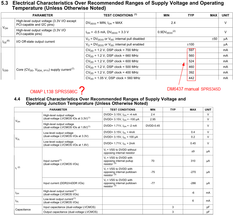


I searched OMAP L138 document sprs58c for typical chip core current without any finding. However, on DM6437 document sprs345d, typical core current in mA are listed.


Why this information is not provided with OMAP L138?


Zhengq


  • Zheng

    Publishing a "typical power" number has little value for hardware designers and power supply sizing assessments.  I am sure DM6437 datasheet also has a foot note that points users to look at the power consumption summary application note and spreadsheet. That is our "standard" way of delivering power consumption information on the device. The user has the flexibility to feed inputs that are close to his/her realistic application scenario, and understand the "worst case" power over temperature and process. 

    For OMAPL138 you can find that information here

    http://processors.wiki.ti.com/index.php/OMAP-L138_Power_Consumption_Summary

    If you still need a typical number, there are macro buttons on the spreadsheet that can convey power numbers for a typical use-case. Generally these numbers are what some times end up in some of our datasheets. However, for any real assessment you should really be looking at the above wiki and xls on the wiki

    Hope this helps 

    Regards

    Mukul 

  • Anonymous
    0 Anonymous in reply to Mukul Bhatnagar

    Mukul,

    You are right. DM6437 datasheet does contain a footnote on the same page which listed the testing condition as:

    sprs345d, p.160 said:

    (7)   Measured under the following conditions:

    1. 60% DSP CPU utilization doing typical activity (peripheral configurations, other housekeeping activities);
    2. DDR2 Memory Controller at 50% utilization (135 MHz), 50% writes, 32 bits, 50% bit switching;
    3. 2 MHz McBSP0 at 100% utilization and 50% switching;
    4. Timer0 at 100% utilization.

    At room temperature (25 C) for typical process ZWT devices. The actual current draw varies across manufacturing processes and is highly application-dependent. DM643x DMP devices are offered in two basic options: lower-power option and high-performance option. Low-power devices offer lower power consumption across temperature and voltage when compared with high-performance devices. However, high-performance devices offer higher operating speeds. For more details on core and I/O activity, high-performance and low-power device power consumption, as well as information relevant to board power supply design, see the TMS320DM643x Power Consumption Summary Application Report (literature number SPRAAO6).

    So these "typical" current are no more than power consumption sheet calculation entries themselves.


    I would like to know how are these values measured in TI labs? And for the spreadsheet, how are the formulas obtained? If I make a customized board myself, since there will be:

    1. different voltage output from TPS65070 pins
    2. several split power planes
    3. different devices on board

    Is it possible, for an ordinary developer, to measure them separately? I perhaps can measure battery current output with a multi-meter and draw a graph, but this is actually measuring the current sum over all on board devices in aggregation, and is much less information and helpful than being able to know each on-board devices individually.

    What is the typical methodology if a developer wants to measure on-board devices' power more precisely? Could you recommend a solution?


    Zheng


  • Zheng

    For power measurements and power application note and spreadsheet creation we use are internal only validation and debug boards, that are designed to individually bring out all major chip power supplies and have the ability to hook them up to bench power supplies. There are several module tests for various design/validation flow that are used for power characterization and coming up with final formulas and models for power estimation. 

    The power estimation spreadsheets serves as a good proxy for customers who don't intend to spend too much design investments on doing their own power characterization (this is over and above the usage of the xls for early developers who don't have silicon/evaluation board etc). 

    For OMAPL138, I recommend also looking at the board that seems to be available from some developers , that will work with the LogicPD EVM, look at the Wattson Adapter board

    http://www.createnewstuff.com/

    regards

    Mukul