This thread has been locked.

If you have a related question, please click the "Ask a related question" button in the top right corner. The newly created question will be automatically linked to this question.

J721EXSOMXEVM: Regarding Creation of .appimage file which can be loaded TI SBL

Part Number: J721EXSOMXEVM
Other Parts Discussed in Thread: UNIFLASH

Tool/software:

Hello Team,

we are using the MCAL package MCUSW_09_00_00_15_CONFIG + ti-processor-sdk-rtos-j721e-evm-09_00_00_02

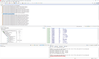
we have developed our own Autosar application stack using TI MCAL, now we have the Application.elf executable file but as per user guide , we need to have ithe application image in .appimage format where SBL can recognize the image and copy the Application image.

Can you please let us know how to convert the existing Application Image in the format of.elf to .appimage which can be loaded by TI SBL

Regards,

Pradeep R

  • Hello Team,

    can you please provide your feedback.

    Regards,

    Pradeep R

  • Hello Tarun,

    we followed the steps mentioned in the above documents but still the control is in TI SBL but not in application

    Please find the below steps followed:

    1 converted our application elf into rprc file using out2rprc.exe 

    2 converted the application rprc file into appimage using MulticoreImageGen.exe

    3 Changed the mode to UART mode

    4 using uniflash tool we run the command dslite.bat --mode processors -c COM22 -f C:\ti\uniflash_8.8.0\processors\FlashWriter\j721e_evm\uart_j721e_evm_flash_programmer_release.tiimage -i 0

    5 using uniflash tool we run the command to load SBL at 0 location of flash

     dslite.bat --mode processors -c COM22 -f sbl_ospi_img_mcu1_0_release.tiimage -d 3 -o 0

    using uniflash tool we run the command to load tifs.bin at 80000 location of flash

    dslite.bat --mode processors -c COM22 -f tifs.bin -d 3 -o 80000

    using uniflash tool we run the command to load application image at 100000 location of flash

    dslite.bat --mode processors -c COM22 -f Application.appimage -d 3 -o 100000

    using uniflash tool we run the command to load nor_spi_patterns.bin at at 3FE0000 location of flash

    dslite.bat --mode processors -c COM22 -f pdk_jacinto_09_00_00_45\packages\ti\board\src\flash\nor\ospi\nor_spi_patterns.bin -d 3 -o 3FE0000

    9 Then powered off the board and changed the mode to OSPI flash mode

    10 Then powered on the board

    when see the memory area, the data is copied into OCMC RAM area for SBL and DDR area for Application,

    In our application, we are using ATCM area from 0x100 onwards for exception table of our application  and complete DDR from 0x80000000 onwards for other segments of application

    when we run the code, the control is always in OCMC RAM region but not in DDR region

    Can you please let me know if any correction needs to be done the flow followed above

    Thankyou

    Regards,

    Pradeep R

  • Hello Tarun,

    Can you please provide us feedback

    Thankyou

    Regards,

    Pradeep R

  • Hello Pradeep,

    Sorry ,In other high priority debug calls, this can be answered next week only.

    Regards

    Tarun mukesh

  • Hello Tarun,

    Sure, Please provide your feedback at the earliest.

    Thankyou

    Regards,

    Pradeep R

  • Hello Tarun,

    Can you please provide us feedback

    Thankyou

    Regards,

    Pradeep R

  • Hello,

    Are you able to see both SBL and TIFS logs on MCU UART ?

    Is this problem with your elf file converted into app image or even with sample example ? or can you try the same steps with sample example we have and see once ?

    Regards

    Tarun Mukesh

  • Hello Tarun,

    I see this issue even with examples.

    I suspect the issue could be the SBL image which i am using.

    Can you please share me the latest SBL image and example that is working at your end.

    So that i can verify same at my end.

    Regards,

    Pradeep R

  • Hello Pradeep,

    SBL image is prebuilt binary and will be part of SDK. If you using the same its not the issue. Connect CCS and see where in the code its exactly halting?

    and also share me the prints on MCU UART.

    Regards

    Tarun Mukesh

  • and also please give paths and names of executable correctly. I don't see paths for SBL,TIFS and application given

    Exampe :

    dslite.bat --mode processors -c COM55 -f C:\ti\uniflash_6.1.0\processors\FlashWriter\j721e_evm\uart_j721e_evm_flash_programmer_release.tiimage -i 0 


    Regards
    Tarun Mukesh
  • Hello Tarun,

    Please find the attached image of Mcu UART terminal, we have an error as part of SBL boot

    dslite.bat --mode processors -c COM22 -f C:\ti\uniflash_8.8.0\processors\FlashWriter\j721e_evm\uart_j721e_evm_flash_programmer_release.tiimage -i 0

    dslite.bat --mode processors -c COM22 -f C:\Pradeep\PradeepR_272723\TI\TDA4\J721E\ti-processor-sdk-rtos-j721e-evm-09_00_00_02\pdk_jacinto_09_00_00_45\packages\ti\boot\sbl\binary\j721e_evm\ospi\bin\sbl_ospi_img_mcu1_0_release.tiimage -d 3 -o 0

    dslite.bat --mode processors -c COM22 -f C:\Pradeep\PradeepR_272723\TI\TDA4\J721E\ti-processor-sdk-rtos-j721e-evm-09_00_00_02\pdk_jacinto_09_00_00_45\packages\ti\drv\sciclient\soc\V1\tifs.bin -d 3 -o 80000

    dslite.bat --mode processors -c COM22 -f C:\Pradeep\PradeepR_272723\TI\TDA4\J721E\udma_memcpy_testapp_freertos\bin\j721e_evm\udma_memcpy_testapp_freertos_mcu1_0_release.appimage -d 3 -o 100000

    dslite.bat --mode processors -c COM22 -f C:\Pradeep\PradeepR_272723\TI\TDA4\J721E\ti-processor-sdk-rtos-j721e-evm-09_00_00_02\pdk_jacinto_09_00_00_45\packages\ti\board\src\flash\nor\ospi\nor_spi_patterns.bin -d 3 -o 3FE0000

    we downloaded the udma_memcpy_testapp_freertos from one of the TI E2E ticket, we did not get this example as part of SDK

    Regards,

    Pradeep R

  • I have assigned this to SBL expert , he will have look into this.

    Regards

    Tarun Mukesh

  • Hello Tarun,

    sure

    Thankyou

    Regards,

    Pradeep R

  • Hi Pradeep,

    when see the memory area, the data is copied into OCMC RAM area for SBL and DDR area for Application,

    it's seems like good.

    when we run the code, the control is always in OCMC RAM region but not in DDR region

    During testing, did you find any errors? Would you please clarify your needs?

    Regards,

    Karthik

  • Hello Karthik,

    As shown below, when we boot from flash, we are getting below error

    when we debugged we found that the DDR region is not enabled by SBL, so can you please provide us an SBL imiage that boots Mcu domain and enables DDR region and copies application into DDR region for execution

    Currently we are using

    dslite.bat --mode processors -c COM22 -f C:\ti\uniflash_8.8.0\processors\FlashWriter\j721e_evm\uart_j721e_evm_flash_programmer_release.tiimage -i 0

    dslite.bat --mode processors -c COM22 -f C:\Pradeep\PradeepR_272723\TI\TDA4\J721E\ti-processor-sdk-rtos-j721e-evm-09_00_00_02\pdk_jacinto_09_00_00_45\packages\ti\boot\sbl\binary\j721e_evm\ospi\bin\sbl_ospi_img_mcu1_0_release.tiimage -d 3 -o 0

    dslite.bat --mode processors -c COM22 -f C:\Pradeep\PradeepR_272723\TI\TDA4\J721E\ti-processor-sdk-rtos-j721e-evm-09_00_00_02\pdk_jacinto_09_00_00_45\packages\ti\drv\sciclient\soc\V1\tifs.bin -d 3 -o 80000

    dslite.bat --mode processors -c COM22 -f C:\Pradeep\PradeepR_272723\TI\TDA4\J721E\udma_memcpy_testapp_freertos\bin\j721e_evm\udma_memcpy_testapp_freertos_mcu1_0_release.appimage -d 3 -o 100000

    dslite.bat --mode processors -c COM22 -f C:\Pradeep\PradeepR_272723\TI\TDA4\J721E\ti-processor-sdk-rtos-j721e-evm-09_00_00_02\pdk_jacinto_09_00_00_45\packages\ti\board\src\flash\nor\ospi\nor_spi_patterns.bin -d 3 -o 3FE0000

    All the above images were already prebuilt in SDK

    Our need is, we will develop our application in DDR region and when boot the TDAVM device from flash, the TI SBL should copy the application from flash into DDR region and execute the application

    Regards,

    Pradeep R

  • Hi Pradeep,

    when we debugged we found that the DDR region is not enabled by SBL, so can you please provide us an SBL imiage that boots Mcu domain and enables DDR region and copies application into DDR region for execution

    It seems like you are using OSPI boot mode,i don't understand how you are getting those errors? and are able get teraterm logs on this OSPI boot mode?

    10 Then powered on the board

    After this, could you please explain the steps?

    we will develop our application in DDR region and when boot the TDAVM device from flash, the TI SBL should copy the application from flash into DDR region and execute the application

    To change your application memory, please refer to the pdk_jacinto_09_02_00_30/packages/ti/build/j721e/linker_r5_freertos.lds file.

    Regards,

    Karthik

  • Hello Karthik,

    It seems like you are using OSPI boot mode,i don't understand how you are getting those errors? and are able get teraterm logs on this OSPI boot mode?

    Feedback : yes we are using OSPI boot mode

    After this, could you please explain the steps?

    Feedback :After power On, immediately on the MCU uart terminal of CCS, we are getting above mentioned error

    To change your application memory, please refer to the pdk_jacinto_09_02_00_30/packages/ti/build/j721e/linker_r5_freertos.lds file.

    Feedback : Already we have taken all the changes required for application in linker file as per user guide provided

    Here , now the issue is , the SBL TI image for OSPI boot which is provided as part of SDK and example application which is provided as part of SDK is not working as expected

    So i Request TI to share the working SBL Ti image along sample example app image and also tifs.bin file which is required,

    Thankyou

    Regards,

    Pradeep R

  • Hi Pradeep,

    So i Request TI to share the working SBL Ti image along sample example app image and also tifs.bin file which is required,

    Please find the attached file let us know if this helps.

    J721e_EVM_9.2_WorkingSample.zip

    Regards,

    Karthik

  • Hello karthik,

    Thankyou for the images, now i can see that control is in application

    To proceed further, i want to know the linker file used to build this application GPIO_Baremetal_LedBlink_TestApp_mcu1_0_release.appimage, can you please share us the memory usage or linker file of this application so that we build our application similar to this.

    I have two more queries 

    1 when we do system reset in CCS, application runs properly

    2 When we do CPU reset in CCS, it gets stucks at one point

    Can you please explain this behaviour

    Thankyou

    Regards,

    Pradeep R

  • Hi Pradeep,

    To proceed further, i want to know the linker file used to build this application GPIO_Baremetal_LedBlink_TestApp_mcu1_0_release.appimage, can you please share us the memory usage or linker file of this application so that we build our application similar to this.

    Please find the attached file:

    8508.linker_r5.zip

    1 when we do system reset in CCS, application runs properly

    Did you use OSPI boot mode or NO boot mode for this test?

    Regards,

    Karthik

  • Hello Karthik,

    Did you use OSPI boot mode or NO boot mode for this test?

    Yes, we are using OSPI boot mode

    Regards,

    Pradeep R

  • Hi Pradeep,

    Yes, we are using OSPI boot mode

    1.Could please clarify when board is OSPI boot mode, why are you trying to load binary from ccs? because binary already loaded through uniflash commanded.

    Regards,

    Karthik 

  • Hello Karthik,

    1.Could please clarify when board is OSPI boot mode, why are you trying to load binary from ccs? because binary already loaded through uniflash commanded.

    Feedback :  we want to debug few symbols and other application related behavior. So we will load symbols in CCS and verify it, but we mainly want to know how this CPU reset and System reset Works

    Regards,

    Pradeep R

  • Hi Pradeep,

    we want to debug few symbols and other application related behavior. So we will load symbols in CCS and verify it,

    In OSPI boot mode, the SBL and the application binary are already loaded into the OSPI flash. Resetting the system or CPU causes potentially disrupting the preloaded binaries. After connecting to the target in CCS, only load the symbols  of your application binary instead of reset or reloading the entire executable.

    , but we mainly want to know how this CPU reset and System reset Works

    1.System Reset resets all cores and  It brings the SoC back to its power-on reset state

    2.CPU Reset resets only the selected core. Other cores and system peripherals remain unaffected.

    Regards,

    Karthik

  • Hello Karthik,

    Thankyou for the feedback regarding reset 

    I have few more questions

    1 After updating linker file of our application as per shared reference(8508.linker_r5.zip), still we are not able to copy our application into DDR and execute from CCS. May i know what could be the issue here?

    2 We tried debugging SBL images which was shared as part of the PDK and we found sbl_cust_img_mcu1_0_release.tiimage and using this SBL, we are able to see in CCS that our application is copied into DDR and executes as expected. May i know what is the difference between  sbl_ospi_img_mcu1_0_release.tiimage and sbl_cust_img_mcu1_0_release.tiimage?

    3 Also we want to know how to generate these SBL images individually, as per user guide ,we have commands to generate all together, but we want to know how to generate individually eg : only sbl_cust_img_mcu1_0_release.tiimage

    Regards,

    Pradeep R

  • Hello Karthik,

    Any feedback here.

    Regards,

    Pradeep R

  • Hi Pradeep,

    After updating linker file of our application as per shared reference(8508.linker_r5.zip), still we are not able to copy our application into DDR and execute from CCS. May i know what could be the issue here?

    Could you help explain the changes made to this file?Would you sharing your map file with me?

    2 We tried debugging SBL images which was shared as part of the PDK and we found sbl_cust_img_mcu1_0_release.tiimage and using this SBL, we are able to see in CCS that our application is copied into DDR and executes as expected. May i know what is the difference between  sbl_ospi_img_mcu1_0_release.tiimage and sbl_cust_img_mcu1_0_release.tiimage?

    sbl_ospi_img:

    Tertiary boot loader which boots main domain cores in stages from OSPI

    sbl_cust_img:

    Flavor of OSPI SBL with custom flags. With this SBL, user can control the following things

    DDR initialization

    Initialization of PLLs

    Initialization of clocks

    Skipping MCU Reset

    3 Also we want to know how to generate these SBL images individually, as per user guide ,we have commands to generate all together, but we want to know how to generate individually eg : only sbl_cust_img_mcu1_0_release.tiimage

    Please refer the below build command :

    make BOARD=j721e_evm CORE=mcu1_0 sbl_cust_img  DISABLE_RECURSE_DEPS=no -sj6
    

    Regards,

    Karthik


  • Hello Karthik,

    Please find the map file of our application

    ARM_TDA4VMCR5_Application_Can.zip

    here vector table of application(EXCTABLE) is placed at 0x100 memory address of ATCM as per user guide

    Regards,

    Pradeep R

  • Hi Pradeep,

    here vector table of application(EXCTABLE) is placed at 0x100 memory address of ATCM as per user guide

    Please refer to the file that is attached below. Sample 1's GPIO application is by default stored in DDR memory, whereas Sample 2's GPIO application is  kept in ATCM memory. You may modify your linker file by following the example provided.

    memory alteration.zip

    Regards,

    Karthik

  • Hello karthik,

    Even after adapting the linker as per provided reference , we are getting issue in running application. Please find the linker and map fileTDA4XEVM.zip

    Our application is Stuck at the Exception Handler

    Also may i know in the provided SBL ti image as part of this (J721e_EVM_9.2_WorkingSample.zip) whether the option "DSBL_SKIP_MCU_RESET" is enabled or not

    Because as per our debugging the exception handler is triggered because of MCU reset.

    If  in case not enabled, can you please enable and provide us the SBL ti image, we will verify it once

    Regards,

    Pradeep R

  • Hi,

    If  in case not enabled, can you please enable and provide us the SBL ti image, we will verify it once

    Please refer the sbl_cust_img which you can control the following things

    • DDR initialization

    • Initialization of PLLs

    • Initialization of clocks

    • Skipping MCU Reset

    Regards,

    Karthik

  • Hello Karthik,

    with cust sbl image it is working for us as i mentioned earlier, the OSPI SBL  image is not working

    May i know, why the Skipping MCU Reset is required for our application and not for sample example with OSPI SBL image.

    Regards,

    Pradeep R

  • Hi,

    May i know, why the Skipping MCU Reset is required for our application and not for sample example with OSPI SBL image.

    If your application relies on specific configurations or data stored in MCU RAM or other MCU-related registers set up during a prior boot stage or warm restart, resetting the MCU would erase this state, and Skipping the reset avoids the additional overhead of reinitializing the MCU subsystem, which could improve boot time.

    Regards,

    Karthik

  • Hello Karthik,

    Thankyou for the information

    Our query regarding app image copying and execution is resolved

    but we have an open query now which i have raised in another ticket regarding OSPI boot mode which is affecting our flash areas, so i how to proceed there?

    Even we tried SD card boot mode but, SD card boot mode takes more time after system reset, it is nearly taking 3 seconds which too high?

    Regards,

    Pradeep R

  • Hi Pradeep,

    Our query regarding app image copying and execution is resolved

    Thank you for the update.

    but we have an open query now which i have raised in another ticket regarding OSPI boot mode which is affecting our flash areas, so i how to proceed there?

    You may close this discussion here, and we'll take up your issue in the new ticket.

    Regards,

    Karthik

  • Hello Karthik,

    Thankyou for the Support

    Can you please help us to provide feedback in the other ticket which i have created

    Regards,

    Pradeep R