Other Parts Discussed in Thread: SYSCONFIG
Tool/software:
Hello,
We want to use the input capture function of the timer, but we don’t see the connection between the timer and the pin in the sysconfig software. Is there any relevant sample program?
Hello Wanglili,
Thanks for your patience.
Is there any relevant sample program?
Currently there are no sample programs when we talk about Timers. This might come up in the future SDK releases.
The only timer example which I can provide as of now is as follows:
"
For AM64x MCU PLUS SDK, I have written a piece of code for demonstrating the timer interrupt.
I have written this application by taking the empty application under mcu_plus_sdk/examples/empty as the baseline.
I am attaching the zip file so that you can go ahead, import to CCS and run it on the go.
empty_am64x-sk_r5fss0-0_nortos_ti-arm-clang.zip
"
Regards,
Vaibhav
Hello,
I understand this usage of timer interrupt. Currently we want to use timer capture, is it not supported yet?Our usage scenario is as follows: Clear the timer value through the interrupt of the GPS pps pulse, and modify the count value of the timer through a period of calculation, in order to achieve the same frequency count as the second pulse.I am currently having some problems,I hope you can help analyze it.
Let me first introduce my application background。
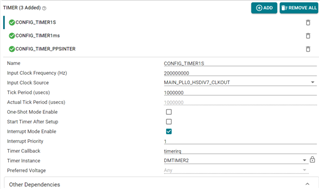
1、A whole second timer is defined with a clock frequency of 200Mhz,Interrupt priority is 1,like list

2、Capture PPS pulses of GPS using capture interrupt

3、When the PPS pulse is received, first turn off the interrupt, and then restore the timer count to the initial value,and then turn on interrupts.


4、Record the current timer count when entering the capture interrupt,Calculate an average value from about 30 count values, and use this average value as the load value of the timer.
 difarr is the reload value.
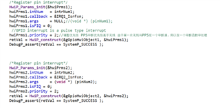
5、Through the calculation of 4, the adjusted timer is basically consistent with the PPS of GPS.There are 2 external interrupts at this time, but the interrupt priority is lower than the capture interrupt.

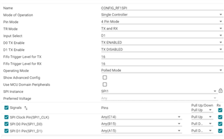
6、When I use SPI to exchange data with external devices, the count of the capture interrupt timer is unstable, and the deviation reaches 4us.However, when the SPI is not running, the timer count error is basically within 1us when the capture interrupt arrives.

7、I also used the system clock for testing, and the result was that the error was 3-4us when using SPI.
Regarding my phenomenon, how can I verify what the problem is?If anything is unclear, please feel free to remind me to add an explanation.
Hello Wanglili,
Thank you for the detailed explanation.
Currently from TI's SW Offering point of view, we are not supporting Timer Capture and Compare.
I will keep any eye on this thread and let you know when we start supporting this feature.
Regards,
Vaibhav
Hi,
OK, thank you very much. But have you read the questions I asked above? When I was using it, I found that the timer count was inaccurate. What could be the problem?Is there an API function that can be called to clear the timer count?
There is another question, how to use FIQ in interrupt mode? When it is set to 1, should its priority be higher than IRQ?
Hi,
I discovered a phenomenon in my testing here. When I run the program on DDR, there will be a big deviation when I use the GPS pair, but when I run the program on MSRAM, there won’t be such a big deviation.This may have nothing to do with the inaccurate timer count I suspect.Is there anything that affects interrupts when operating DDR? What are the parameters related to DDR?
Hello Wanglili,
Please allow sometime for another expert to comment on this.
Regards,
Vaibhav
Hello Wanglili,
A timer module is available on AM64X. This timer can be supported to measure the PWM parameters and the driving PWM signal.
You can use the Timer module for capturing PWM signals.
Please look at the FAQ below and TRM chapters below to make the changes to capture mode.
I have created an FAQ for Generating PWM from the Time module and the same procedure can be applied for capture mode as well.


Regards,
Anil.
Hi,
I have just come into contact with AM64 SOC. It is a bit difficult for me to configure this register by myself. Can you provide us with a sample program for reference?It would be great if you could.
Hi wanglili,
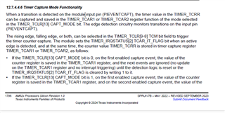
If you look at the above FAQ and TRM image for capturing mode.
You can easily do it and there are few registers to configure timer in capture mode.
Please check the FAQ code and create an example for timer in capturing mode.
Since, the same PWM steps you need to follow for the capture mode.
Regards,
Anil.
Hello,
I configured the capture mode based on the PWM example you provided. After the current configuration, I checked the register to confirm that the configuration has been completed, but currently I can not receive the captured signal. I need your help in analyzing where the problem may occur regarding this part?
I use U7 pin of timer7 for capture,The timer clock frequency is 200MHZ, and the overflow interrupt period is 1S.I did not find the problem with my configuration. I hope you can help find the problem.Thank you very much。
void Timer_config(void)
{
     TimerP_Params timerParams;
     HwiP_Params timerHwiParams;
     int32_t status;
     volatile uint32_t *addr;
     uint32_t ctrlVal = 0x00;

     /* set timer clock source */
     SOC_controlModuleUnlockMMR(SOC_DOMAIN_ID_MAIN, 2);
     *(volatile uint32_t*)AddrTranslateP_getLocalAddr(0x430081CC) = 2;
     SOC_controlModuleLockMMR(SOC_DOMAIN_ID_MAIN, 2);

     gTimer7BaseAddr = (uint32_t)AddrTranslateP_getLocalAddr(0x2470000u);

     TimerP_Params_init(&timerParams);
     timerParams.inputPreScaler = 1;
     timerParams.inputClkHz     = 200000000u;
     timerParams.periodInNsec   = 1000000000u;
     timerParams.oneshotMode    = 0;
     timerParams.enableOverflowInt = 1;
     timerParams.enableDmaTrigger  = 0;


     TimerP_setup(gTimer7BaseAddr, &timerParams);
     addr = (volatile uint32_t *)(gTimer7BaseAddr + 0x38);

     ctrlVal =  ( (1<<1U) | (1<<14U)| (1<<8U) | (1<<5U) ); //Trigger on overflow, Toggle, enable Auto Reload Mode
     *addr = ctrlVal;

     addr = (volatile uint32_t *)(gTimer7BaseAddr + 0x2c);
     ctrlVal = (0x1U << 2)|(0x1U << 1);
     *addr = ctrlVal;

     HwiP_Params_init(&timerHwiParams);
     timerHwiParams.intNum = 159;
     timerHwiParams.callback = Timer7_isr0;
     timerHwiParams.isPulse = 0;
     timerHwiParams.priority = 2;
     status = HwiP_construct(&gTimerHwiObj[CONFIG_TIMER1S], &timerHwiParams);
     DebugP_assertNoLog(status==SystemP_SUCCESS);

     Pinmux_PerCfg_t Timer_pin_Cfg[] =
     {
        {
             PIN_PRG1_PRU0_GPO17,//U7
            ( PIN_MODE(6)  | PIN_PULL_DISABLE )
        },

        {PINMUX_END, PINMUX_END}
     };

     Pinmux_config(Timer_pin_Cfg, PINMUX_DOMAIN_ID_MAIN);
     TimerP_start(gTimer7BaseAddr);//start timer
}
void Timer7_isr0(void *args)
{
//    void timerirq(void *args);
    uint32_t value = 0x00;
    uint32_t timercnt=0;

    /* clear status for overflow interrupt */
    value = CSL_REG32_RD(gTimer7BaseAddr + 0x28);

    if(value & (0x1U << 1))//overflow
    {
        value = (0x1U << 1) ;
        CSL_REG32_WR((gTimer7BaseAddr + 0x28), value);
        timerirq(args);
    }
    if(value & (0x1U << 2))//capture
    {
        value = (0x1U << 2) ;
        CSL_REG32_WR((gTimer7BaseAddr + 0x28), value);
        timercnt = CSL_REG32_RD(gTimer7BaseAddr + 0x50);
        timercnt = timercnt - (0xffffffff-(200000000-1));
        PPS_IsrFxn1(timercnt,0);
    }
    TimerP_clearOverflowInt(gTimer7BaseAddr);
    HwiP_clearInt(159);
}Hello,
You may get reply on 2nd Jan, and today I am busy on other escalations.
Apologies for delayed replies.
Regards,
Anil.
Hi Wanglili,
The subject matter expert is currently out of office for this & next week. Please expect a delayed response. Thanks for your patience.
Regards,
Tushar