Other Parts Discussed in Thread: TDA4VH
Tool/software:
Hello,
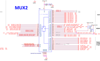
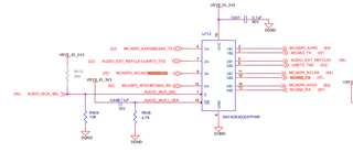
I am trying to enable MCAN5 on the TDA4VH EVM by modifying the device tree. Since I added NCAN5-related nodes the device shows up under /proc and /sys/class/net however I am not able to send CAN frames through the transceiver (I am able to use the CAN5 in loopback mode though). I suspect my standby or pinctrl definitions are not correct. Since the STB pin is on the expander I was not sure how to properly declare it in the transceiver node. Could you please help me with the CAN configuration?
// SPDX-License-Identifier: GPL-2.0
/dts-v1/;
/plugin/;
#include <dt-bindings/gpio/gpio.h>
#include "k3-pinctrl.h"
#define R_CAN_STB 7 /*P7*/ //MCAN5_STB
#define CANUART_MUX_SEL0_GPIO 13 /*P15*/
#define CANUART_MUX2_SEL1_GPIO 14 /*P16*/
#define CANUART_MUX1_SEL1_GPIO 15 /*P17*/ //unused in this file
#define USER_LED1_GPIO 22 /*P26*/
#define USER_LED2_GPIO 23 /*P27*/
// aliases {
// mcan5 = "main_mcan5";
// };
&exp2 {
/* User LEDs */
user-led1 {
gpio-hog;
gpios = <USER_LED1_GPIO (GPIO_ACTIVE_HIGH | GPIO_PULL_DOWN)>;
output-low; /* Start with LED on */
line-name = "USER_LED1";
};
user-led2 {
gpio-hog;
gpios = <USER_LED2_GPIO (GPIO_ACTIVE_HIGH | GPIO_PULL_DOWN)>;
output-high; /* Start with LED off */
line-name = "USER_LED2";
};
//can standby
/*MCAN5_STB*/
r_can_stb {
gpio-hog;
gpios = <R_CAN_STB (GPIO_ACTIVE_HIGH | GPIO_PULL_UP)>;
line-name = "MCAN5_STB";
};
/*canuart pinmux*/
// for MCAN5, MCAN4(mux2) and MCAN3(mux1)
// shared betweeen both muxes
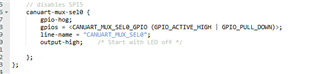
// disables SPI5
canuart-mux-sel0 {
gpio-hog;
gpios = <CANUART_MUX_SEL0_GPIO (GPIO_ACTIVE_HIGH | GPIO_PULL_DOWN)>;
line-name = "CANUART_MUX_SEL0";
output-high; /* Start with LED off */
};
};
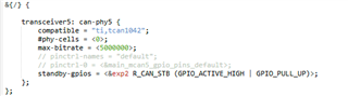
&{/} {
transceiver5: can-phy5 {
compatible = "ti,tcan1042";
#phy-cells = <0>;
max-bitrate = <5000000>;
// pinctrl-names = "default";
// pinctrl-0 = <&main_mcan5_gpio_pins_default>;
standby-gpios = <&exp2 R_CAN_STB (GPIO_ACTIVE_HIGH | GPIO_PULL_UP)>;
};
};
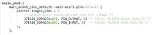
&main_pmx0 {
main_mcan5_pins_default: main-mcan5-pins-default {
pinctrl-single,pins = <
/* Adjust these based on your specific pinmux */
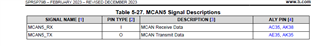
J784S4_IOPAD(0x038, PIN_OUTPUT, 0) /* (AK35) MCASP0_ACLKX.CAN5_TX */
J784S4_IOPAD(0x03C, PIN_INPUT, 0) /* (AK38) MCASP0_AFSX.CAN5_RX */
>;
};
// main_mcan5_gpio_pins_default: main-mcan5-gpio-pins-default {
// pinctrl-single,pins = <
// >;
// };
};
&main_mcan5 {
status = "okay";
pinctrl-names = "default";
pinctrl-0 = <&main_mcan5_pins_default>;
phys = <&transceiver5>;
};
Thanks in advance