SK-AM62A-LP: [SDK 10.00.00] SPI D0 and D1 pins assigned to MOSI and MISO

Part Number: SK-AM62A-LP
Other Parts Discussed in Thread: SYSCONFIG

Tool/software:

Hello,

I'm trying to use SPI0 as a Master in linux. I updated the DTS accordingly to assign the needed pins.

You can find the changes to DTS file below:

main_spi0_pins_default: main-spi0-default-pins {
pinctrl-single,pins = <
AM62AX_IOPAD(0x1c0, PIN_OUTPUT, 0) /* (B15) SPI0_D0 */
AM62AX_IOPAD(0x1c4, PIN_INPUT, 0) /* (E15) SPI0_D1 */
AM62AX_IOPAD(0x1b4, PIN_OUTPUT, 0) /* (D16) SPI0_CS0 */
AM62AX_IOPAD(0x1bc, PIN_OUTPUT, 0) /* (A17) SPI0_CLK */
>;
};

&main_spi0 {
pinctrl-names = "default";
pinctrl-0 = <&main_spi0_pins_default>;
status = "okay";
spidev@0 {
spi-max-frequency = <24000000>;
reg = <0>;
compatible = "rohm,dh2228fv";
};
};

I tried to test it using the test application found in ./tools/spi/

The query here is how to identify whether D0 assigned to MOSI or MISO?

I was expecting D0 assigned to MOSI and D1 assigned to MISO.

But the actual behavior is data sent over pin SPI0_D1 which means it acts as MOSI

How to identify/assign pins to MOSI and MISO?

Another query, What If I want to use spidev to test SPI0 as a slave?

Thank you,

  • Hi Ramy,

    The query here is how to identify whether D0 assigned to MOSI or MISO?

    I was expecting D0 assigned to MOSI and D1 assigned to MISO.

    By default, D0 is MISO, and D1 is MOSI. There is a device-tree property called ti,pindir-d0-out-d1-in that reverses the default order. Looking up the associated device tree node binding documentation always helps remembering what is what:

    a0797059@jiji:~/git/linux (master)
    $ git grep -A 5 ti,pindir-d0-out-d1-in\:
    Documentation/devicetree/bindings/spi/omap-spi.yaml:  ti,pindir-d0-out-d1-in:
    Documentation/devicetree/bindings/spi/omap-spi.yaml-    description:
    Documentation/devicetree/bindings/spi/omap-spi.yaml-      Select the D0 pin as output and D1 as input. The default is D0
    Documentation/devicetree/bindings/spi/omap-spi.yaml-      as input and D1 as output.
    Documentation/devicetree/bindings/spi/omap-spi.yaml-    type: boolean
    Documentation/devicetree/bindings/spi/omap-spi.yaml-

    Another query, What If I want to use spidev to test SPI0 as a slave?

    We don't officially support SPI slave operation with the Linux SDK/driver. While there's ways to make it work there are some constraints, and you would be better off using a different communication scheme (high-speed UART, for example -- but that really depends on your system).

    Regards, Andreas

  • Hi Andreas,

    Thank you for your quick response.

    Adding device-tree property ti,pindir-d0-out-d1-in reversed the pins.

    Regarding the SPI slave, I get that it's not supported officially, But Do you have any guide/manual/steps on what changes need to be done to have SPI working as Slave?

    Best Regards,

  • Hi Ramy,

    Regarding the SPI slave, I get that it's not supported officially, But Do you have any guide/manual/steps on what changes need to be done to have SPI working as Slave?

    In essence, you need to add DMA-related properties (dmas and dma-names) to the device tree node, and then also add spi-slave to the SPI peripheral device tree node, like this:

    $ git show
    commit 30253dd73e444c451cf352b2b005d32e03b080be (HEAD -> ti-linux-6.6.y-spi-slave-dev)
    Author: Andreas Dannenberg <dannenberg@ti.com>
    Date:   Wed Nov 13 15:15:04 2024 -0600
    
        arm64: dts: ti: k3-am62a: Configure SPI0 as Slave-Mode spidev Device
    
        Note that the SPI Slave in Linux doesn’t implement flow-control by default
        and custom flow control mechanism need to be implemented according to the
        application for deterministic performance.
    
        Signed-off-by: Andreas Dannenberg <dannenberg@ti.com>
    
    diff --git a/arch/arm64/boot/dts/ti/k3-am62a7-sk.dts b/arch/arm64/boot/dts/ti/k3-am62a7-sk.dts
    index 3047586a6d9d..b582f08d1fe1 100644
    --- a/arch/arm64/boot/dts/ti/k3-am62a7-sk.dts
    +++ b/arch/arm64/boot/dts/ti/k3-am62a7-sk.dts
    @@ -451,6 +451,15 @@ AM62AX_IOPAD(0x028, PIN_INPUT, 0) /* (J22) OSPI0_D7 */
                            AM62AX_IOPAD(0x008, PIN_INPUT, 0) /* (J24) OSPI0_DQS */
                    >;
            };
    +
    +       main_spi0_pins_default: main-spi-pins-default {
    +               pinctrl-single,pins = <
    +                       AM62AX_IOPAD(0x01bc, PIN_INPUT, 0) /* (A17) SPI0_CLK */
    +                       AM62AX_IOPAD(0x01b4, PIN_INPUT, 0) /* (D16) SPI0_CS0 */
    +                       AM62AX_IOPAD(0x01c0, PIN_INPUT, 0) /* (B15) SPI0_D0 */
    +                       AM62AX_IOPAD(0x01c4, PIN_INPUT, 0) /* (E15) SPI0_D1 */
    +               >;
    +       };
     };
    
     &mcu_pmx0 {
    @@ -944,3 +953,25 @@ partition@7fc0000 {
                    };
            };
     };
    +
    +&main_spi0 {
    +               status = "okay";
    +               #address-cells = <0>;
    +               #size-cells = <0>;
    +               pinctrl-names = "default";
    +               pinctrl-0 = <&main_spi0_pins_default>;
    +               ti,pindir-d0-out-d1-in = <1>;
    +               spi-slave;
    +               dmas = <&main_pktdma 0xc300 0>, <&main_pktdma 0x4300 0>;
    +               dma-names = "tx0", "rx0";
    +
    +               slave {
    +                               /*
    +                                * Using spidev compatible is warned loudly,
    +                                * thus use another equivalent compatible id
    +                                * from spidev.
    +                                */
    +                               compatible = "rohm,dh2228fv";
    +                               spi-max-frequency = <24000000>;
    +               };
    +};

    Then when you boot, you can find the slave device here:

    root@am62axx-evm:/opt/edgeai-gst-apps# ls -al /dev/spi*
    crw------- 1 root root 153, 0 Jan  1 00:00 /dev/spidev1.0
    
    root@am62axx-evm:/opt/edgeai-gst-apps# ls -al /sys/class/spi_slave/
    total 0
    drwxr-xr-x  2 root root 0 Jan  1 00:08 .
    drwxr-xr-x 81 root root 0 Jan  1 00:08 ..
    lrwxrwxrwx  1 root root 0 Jan  1 00:08 spi1 -> ../../devices/platform/bus@f0000/20100000.spi/spi_slave/spi1

    And then you _should_ be able to try it like this using spidev_test. In my case it hangs because I don't have anything that's clocking in data...

    root@am62axx-evm:/opt/edgeai-gst-apps# ./spidev_test -D /dev/spidev1.0 -v -p "12345678"
    spi mode: 0x0
    bits per word: 8
    max speed: 500000 Hz (500 kHz)

    Here are some applicable E2E threads with additional information that might be helpful:

    https://e2e.ti.com/support/processors-group/processors/f/processors-forum/1262607/am3351-linux-support-for-spi-as-a-slave-device/4780250

    https://e2e.ti.com/support/processors-group/processors/f/processors-forum/1301459/tda4al-q1-regarding-mcu-spi-slave-mode-configuration-issues

    Please let me know if you get it to work; it will be helpful for everybody if you can share your findings.

    Thanks, Andreas

  • Hi Andreas,

    Thank you for your support.

    Now I have managed to use Main_SPI0 as a slave successfully after following your steps.

    But I have 2 queries:

    1. It's observed that the data is flipped (MSB is used), so I tried to use -L option to use LSB, but as you can see in the above image that the data is not parsed correctly or even in LSB. What may cause such issue?
    2. Why both D0 and D1 is configured as INPUT? I thought we should set D0 to OUTPUT as it's assigned to MISO.

    Best Regards.

  • Hi Ramy,

    It's observed that the data is flipped (MSB is used), so I tried to use -L option to use LSB, but as you can see in the above image that the data is not parsed correctly or even in LSB. What may cause such issue?

    I don't fully understand your system setup and what is expected from the screenshot you provided but generally speaking it could also be because of unsuitable clock/phase settings being used. When I looked at this before I found there's only certain combinations that can be used based on the initial state of the (clock) signal, etc. For example, I had to use the `-H` parameter (clock phase) to get it to work properly.

    Here's a working example that demonstrates slave mode using an external known-good SPI host adapter (always good to "divide and conquer" when debugging): https://e2e.ti.com/support/processors-group/processors/f/processors-forum/1397539/processor-sdk-am335x-how-to-configure-spi-master-slave-mode-with-sdk9/5366588#5366588  Note the clock/phase settings used there as well.

    Why both D0 and D1 is configured as INPUT? I thought we should set D0 to OUTPUT as it's assigned to MISO.

    The pinctrl-single,pins device tree settings affects the padcontrol registers, which contain a long list of different bits that configure the behavior of each pin. Setting it to INPUT is really just using a DTS macro that turns on the transmitter and receiver capability on this pin; so it's as safe choice for those SPI pins to always work no matter if you reverse D0 vs. D1 as discussed earlier. The actual input/output behavior will be controlled by the peripheral module that is selected, in this case the SPI module.

    Note that interestingly some output pins actually require to be configured as "INPUT" from the device tree / padcontrol register perspective for things to work properly, see https://e2e.ti.com/support/processors-group/processors/f/processors-forum/1263441/sk-am62-no-spi-signals-on-expansion-headers/4784405#4784405

    Best is to simply stick to the pin direction definitions that are already used in the DTS, or are generated using the SysConfig tool.

    Regards, Andreas

  • Hi Andreas,

    Thank you for your continuous support.

    I confirmed that the clock/phase setting is correct and already using -H parameter. What I meant previously is that the data is represented in most significant bit format not least significant bit format. I tried to use -L option but it failed.

    Actually I have another clarification, Do I need to change anything other than the pins to use SPI2 as a slave.

    Any changes related to the DMA for example?

    DTS changes attached below.

    	main_spi0_pins_default: main-spi0-default-pins {
    		pinctrl-single,pins = <
    			AM62AX_IOPAD(0x1c0, PIN_INPUT, 0) /* (B15) SPI0_D0 */
    			AM62AX_IOPAD(0x1c4, PIN_OUTPUT, 0) /* (E15) SPI0_D1 */
    			AM62AX_IOPAD(0x1b4, PIN_OUTPUT, 0) /* (D16) SPI0_CS0 */
    			AM62AX_IOPAD(0x1bc, PIN_OUTPUT, 0) /* (A17) SPI0_CLK */
    		>;
    	};
    		main_spi2_pins_default: main-spi2-default-pins {
    		pinctrl-single,pins = <
    			AM62AX_IOPAD(0x194, PIN_OUTPUT, 1) /* (C19) SPI2_D0 */
    			AM62AX_IOPAD(0x198, PIN_INPUT, 1) /* (B19) SPI2_D1 */
    			AM62AX_IOPAD(0x1ac, PIN_INPUT, 1) /* (B21) SPI2_CS 0x1ac or A19 0x1A4*/
    			AM62AX_IOPAD(0x1b0, PIN_INPUT, 1) /* (A21) SPI2_CLK */
    		>;
    	};
    	
    	
    &main_spi0 {
    	pinctrl-names = "default";
    	pinctrl-0 = <&main_spi0_pins_default>;
        status = "okay";
    	spidev@0 {
                    spi-max-frequency = <24000000>;
                    reg = <0>;
                    compatible = "rohm,dh2228fv";
            };
    };
    
    &main_spi2 {
    	pinctrl-names = "default";
    	pinctrl-0 = <&main_spi2_pins_default>;
        status = "okay";
    	ti,pindir-d0-out-d1-in;
    	spi-slave;
    	dmas = <&main_pktdma 0xc300 0>, <&main_pktdma 0x4300 0>;
    	dma-names = "tx0", "rx0";	
    
    	slave {
                    spi-max-frequency = <24000000>;
                    compatible = "rohm,dh2228fv";
            };
    
    	spidev@0 {
                    spi-max-frequency = <24000000>;
                    reg = <0>;
                    compatible = "rohm,dh2228fv";
            };
    };

    Best regards,

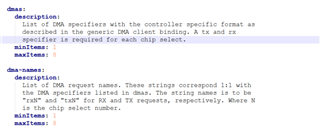
  • Another point, I noticed from Documentation/devicetree/bindings/spi/omap-spi.yaml that following:

    In the dmas-names property, it's mentioned to order the "rxN" then the "txN", while previously I tested with the reverse order and it was working correctly with SPI0.

    Would that cause any issues?

  • Hi Andreas,

    I just wanted to update you that I've been able use SPI2 as a slave after updating the PSI-L thread ID.

    Attaching the DTS changes below.

    &main_spi2 {
    	pinctrl-names = "default";
    	pinctrl-0 = <&main_spi2_pins_default>;
        status = "okay";
    	ti,pindir-d0-out-d1-in;
    	spi-slave;
    	dmas = <&main_pktdma 0xc308 0>, <&main_pktdma 0x4308 0>;
    	dma-names = "tx0", "rx0";	
    
    	slave {
                    spi-max-frequency = <24000000>;
                    compatible = "rohm,dh2228fv";
            };
    
    };