Other Parts Discussed in Thread: TDA4VH
Tool/software:
power sequence for TDA4VH - j784s4 . FreeROS
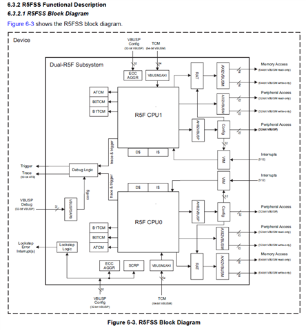
In TDA4 we are having 3 main R5FSS and 1 MCU R5FSS. As we are referring the TRM for TDA4 we have seen the block diagram from R5FSS. we are assuming that all 3 main R5FSS having same interfaces explained in TRM.
but where we can check about the MCU R5FSS.? especially if we divide MCU cortex R5FSS has 2 cores 0_0 & 0_1 core.
can you describe the exact roles of MCU domain R5F0_0 and R5F0_1.
Can you please let me know the way to find out the list of components connected to each R5F core.
My end goal is to identify the components connected to each R5F core and execute it asper the expectation when when power UP & DOWN sequence.
this I should implement in FreeRTOS.
is PMIC only taking care for all power UP and DOWN sequence for each core in TDA4.?
If so we have to take a look in PMIC driver only to rearrange the order of power up and down for R5F interfaces.?
please let me know the way for solution


