J721S2XSOMXEVM: Help tuning DCC CFAI+WDR Pluging

Part Number: J721S2XSOMXEVM

Tool/software:

Hello Ti experts,

I'm working on DCC tuning with RYYCy sensor, and trying to correct color.

Even before getting the color tuned, I'm stuck on brightness issue.

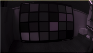
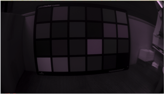
The sensor configuration is RYYCy Raw12, and I can capture raw image as below.
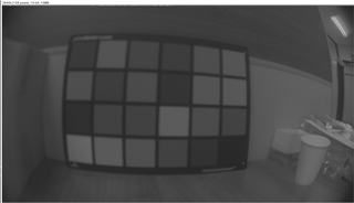
< image_raw.raw >

When I tune CFAI setting 24bit Decompanding bit, Knee Points, and CCM on CFAI+WDR(VPAC3),
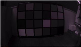
processing the plugin, and then "Updates the current plugin DCC file", the yuv output is captured as below.
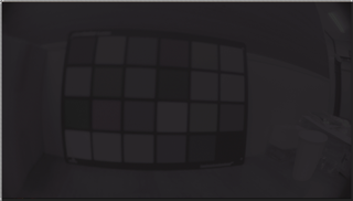
< image_viss_updated_by_cfai_plugin.yuv >

I tested the CCM matrix manipulating serveral times, I don't think it affects to yuv output.

Then I tried those generated parameter files with generate_dcc.sh.
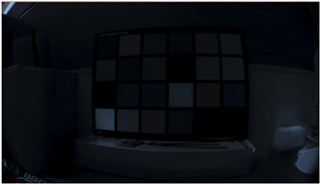
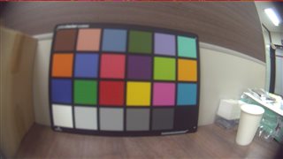
When I apply dcc bins generated by generate_dcc.sh results in very dark output as below.

< image_viss_dcc_bins.yuv >

I don't think even the tuning result of CFAI plugin updated by the tool isn't correct, but more frustrating thing is that the dcc bins generated by the xml files from that plugin results in wired and different output.

There must be something I'm missing.

I have attached the DCC configuration, XML files, and captured images including raw image, please let me know what is wrong.

 ryycy_dcc_tuning.zip

Regards,

Juhyun

  • Hi Juhyun,

    The sensor configuration is RYYCy Raw12, and I can capture raw image as below.

    Could you please remind me which sensor are you working on?

    When I tune CFAI setting 24bit Decompanding bit, Knee Points, and CCM on CFAI+WDR(VPAC3),

    Did you used the python script to get your initial VISS settings?
    https://e2e.ti.com/support/processors-group/processors/f/processors-forum/1275034/faq-default-dcc-profile-generation-tool-for-tda4-am6xa-isp-vpac?tisearch=e2e-sitesearch&keymatch=%20user%3A35541

    If you did, do you get brighter output image at VISS output?

    Starting with python script is typically easier than the tuning tool as there are much fewer number of input parameters.

    I tested the CCM matrix manipulating serveral times, I don't think it affects to yuv output.

    CCM tuning does not change VISS input and output image brightness.
    The issue is more related to tone mapping and sensor exposure control (AE and sensor driver).

    If the raw image from sensor is too dark or tone mapping is not set up properly, VISS output image could be dark.

    I have attached the DCC configuration, XML files, and captured images including raw image, please let me know what is wrong.

    Thanks for sharing your settings and raw/yuv images.

    I would recommend starting with the python script to get initial xml files using the simple configuration files as in below examples.
    Please follow the instructions in the comments.
    https://git.ti.com/cgit/processor-sdk/imaging/tree/tools/default_DCC_profile_gen/configs/imx390_properties.txt?h=main
    https://git.ti.com/cgit/processor-sdk/imaging/tree/tools/default_DCC_profile_gen/configs/imx219_properties.txt?h=main

    You may also refer to this app note for some more details https://www.ti.com/lit/pdf/sprad86

    There must be something I'm missing.

    I see that you try to program the CCM in CFAI plugin.
    I would suggest that you start with the color correction plugin for CCM tuning instead.
    Using the new features in VPAC3 CFAI may be confusing for you.
    You may start with the python script output settings for VPAC1 CFAI as a baseline.
    Once you get correct exposure and color, you may move to tuning tool to make finer adjustment.

  • BTW, it looks like your raw image is in YRCyY format with good color, but your YUV output image has completely wrong color (not just dark).

    Starting with python script, you may get some reasonable color first (as good as raw image).

  • Hi Gang,

    Could you please remind me which sensor are you working on?

    The sensor is S5K1H1SB, and I have managed to bring it up by creating the sensor driver.

    Did you used the python script to get your initial VISS settings?

    Yes, I initially used the python script and worked on the settings generated from it as a base xml settings.

    CCM tuning does not change VISS input and output image brightness.
    The issue is more related to tone mapping and sensor exposure control (AE and sensor driver)

    The driver I made doesn't control AE at this development stage.

    I would suggest that you start with the color correction plugin for CCM tuning instead.
    Using the new features in VPAC3 CFAI may be confusing for you.
    You may start with the python script output settings for VPAC1 CFAI as a baseline.
    Once you get correct exposure and color, you may move to tuning tool to make finer adjustment.

    I see, I tried again from the very first stage generating xml files from the properties txt file as you guided.

    This is raw image.

    < image_raw_20241212.raw >

    And this is the VISS output with the dcc parameters generated from the default properties file, which is based on imx390_proeprties.txt and customized.

    < image_viss_dcc_bins_default_script_20241212.yuv >

    After checking the default result above, I tried RGB2RGB tuning as you said, following the guide,
    the result is as below.

    < image_viss_dcc_bins_rgb2rgb_tuned_20241212.yuv >

    I can't tell the tuning actually takes effect. I don't see the difference.

    This was the reason I tried CFAI3 CCM in the first place.

    Anyway, I tried RGB2RGB tuning as below following the TI guide.

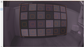
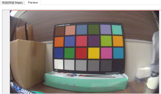
    first, I set the input raw image and marked the checker box region

    second, also set the reference checker image which was included in dcc tool and marked the checker box region.

    Then I processed the plguin, and I got the result as below.

    The preview above was not very good, but I could see a little bit improvement at least.

    But as I already stated above, the actual viss output wasn't like the plugin result preview, and little different from the default as I saw.

    There were some differences in the matrix generated by the tool between displayed one on GUI and the one in xml file,
    and I tried both, the results were the same.

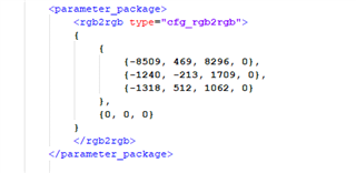
    I even tested the extreme setting to see if the rgb2rgb matrix actually worked, by modified the matrix as below.

    The result viss output was as below.

    < image_viss_dcc_bins_rgb2rgb_extreme_20241212.yuv >

    I don't think the setting works at all.

    I have attatched the images and the configuration and parameter files.

    ryycy_dcc_tuning_241212.zip

    Always thanks for your kind help, Gang.

    Regards,

    Juhyun
  • I have found the reason the rgb2rgb matrix didn't take effect.

    It turned out that the missing implementation of getExpRrg callback in my sensor driver seemed to casue the problem.

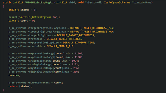
    I have set aewbMode as ALGORITHMS_ISS_AEWB_MODE_AE and implemented getExpPrg by referencing sensor drivers, as following,

    After the setting of aewbMode and implementation of getExpPrg, the rgb2rgb matrix is applied to the viss output.

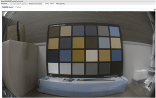
    And furthermore, I have got the color matrix which results in quite good color output on rgb2rgb plugin preview result.

    Now I only need the actual viss output should come out as the rgb2rgb plugin preview result,
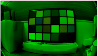
    but I just ended up with different and weired result as below.

    What could cause the difference between rgb2rgb result preview and actuall viss output?

    Regards,

    Juhyun

  • Hi Juhyun,

    And furthermore, I have got the color matrix which results in quite good color output on rgb2rgb plugin preview result.

    That looks correct RGB color, but that is without any color correction applied.

    This is what you shall get in tuning tool for the raw image sample you shared previously.

  • Wow, that is perfect. How could you get the color with the image I shared?

  • Hi Juhyun,

    How could you get the color with the image I shared?

    It is the same process as outlined in the app note https://www.ti.com/lit/pdf/sprad86

    You just need to use the "color correction" plugin of tuning tool, choose the "semi-automatic" mode, and input the raw image and the decompanding knee points.

  • but I just ended up with different and weired result as below.

    I am not sure why you have the dark output YUV image.
    Your share raw image looks OK to me.

    You may try the latest python script in the link below as I have updated it recently.

    https://git.ti.com/cgit/processor-sdk/imaging/tree/tools/default_DCC_profile_gen?h=main

    For your sensor, you may use the settings below as your python script input (please change sensor id to yours).
    That works well with your shared raw sample image.
    Then you may update "S5K1H1SB_rgb2rgb_dcc.xml" with your tuning tool results.

    SENSOR_ID 5
    PRJ_DIR ../RYYCy_output
    SENSOR_NAME S5K1H1SB
    SENSOR_DCC_NAME S5K1H1SB
    
    SENSOR_WIDTH 3840
    SENSOR_HEIGHT 2168
    
    # 0=RGGB;  1=GRBG;  2=GBRG;  3=BGGR,  4=MONO,
    #10=RGGI, 11=GRIG, 12=BGGI, 13=GBIG, 14=GIRG, 15=IGGR, 16=GIBG, 17=IGGB
    COLOR_PATTERN 1
    
    # sensor mode: 0 for linear (no decompanding), 1 for WDR (decompanding)
    WDR_MODE 1
    
    # raw sensor image BIT_DEPTH: it may be 8, 10, or 12 for linear sensors; typically 12 for WDR mode because of companding
    BIT_DEPTH 12
    
    # WDR BIT_DEPTH: WDR raw sensor image bitdepth after decompanding, typically 20 or 24
    WDR_BIT_DEPTH 24
    
    # WDR decompanding knee points (comma separated without spaces in between)
    WDR_KNEE_X 0,512,640,768,1024,1280,1536,2048,2176,2304,2432,2688,2944,3200,4095
    WDR_KNEE_Y 0,512,1024,2048,4096,8192,16384,32768,65536,131072,262144,524288,1048576,2097152,16777215
    
    # Sensor black level to subtract before decompanding (for some Sony WDR sensors)
    # When PCID is on for RGBIR sensors, black level might be set to 0
    BLACK_PRE  0
    
    # Sensor black level to subtract after decompanding (for most WDR sensors and all linear sensors)
    # When PCID is on for RGBIR sensors, black level might be set to 0
    BLACK_POST 0
    
    # GAMMA value for compressing 20/24-bit WDR raw to 16-bit ISP internal
    # typically around 50 (0.5) for 24-bit WDR sensors and 70 (0.7) for 20-bit sensors
    GAMMA_PRE 50
    
    # LSB location for H3A input bit range (from bit-H3A_INPUT_LSB to bit-H3A_INPUT_LSB+9) 
    H3A_INPUT_LSB 4
    
    # Choose the default gamma curve used for YUV output: 0 for BT709, 1 for a high contrast gamma curve
    YUV_GAMMA 1
    

  • BTW, I am not sure what is pedestal value of your sensor and I used 0 above.
    Please update as necessary.

  • I followed the way you guided me to tune RGB2RGB, and I was able to reproduce the result as you did.

    Yes, it was due to the CFA format, it was YRCyY as you corrected, not RYYCy.

    Now as the CCM was secured, I tried the properties.txt you shared gererating the parameters with rgb2rgb ccm parameter tuned to check the ISP result with them on the board.

    I actually tried both configurations without YUV_GAMMA and with YUV_GAMMA after patched recently updated python scripts to generate gamma parameters that you commented on. The YUV_GAMMA version gave better contrast and brightness.

    This was the result.

    I could see the greenish color all around, but the colors themselves of the patches on the color chart seemed correct.

    I thought the greenish could be fixed by white balance, so I went for the awb.

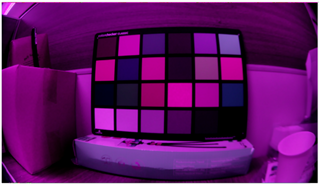
    firstly I enabled awb in the sensor driver and this was the result without tuning on it.

    Currently I don't have the equipment to control the light temperature, so I decided to manually adjust the white balance.

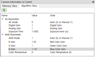
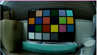
    I could manage to manually set the R/B gains as above, and then get the below result.

    It may not be perfect yet, but it is still an accomplishement for me.

    Thank you so much for that, Gang, without you, I would not have been able to make it this far.

    Now I have to figure out how to apply wb manually tuned, out of the dcc tool.

    Could you give me an advice for that?

    And another question I have, do I need to tune BLC additionally using the plugin?

    I applied the pedestal value on properties.txt, but the values in generated blc xml were 0s.

    Regards,

    Juhyun
  • Hi Juhyun,

    Now I have to figure out how to apply wb manually tuned, out of the dcc tool.

    Could you give me an advice for that?

    AWB has to be calibrated in tuning tool so that it can work properly without manually settings WB gains.
    The python script only creates dummy AWB calibration as a placeholder.

    Please follow the app note and tuning tool plugin guide for AWB calibration.

    And another question I have, do I need to tune BLC additionally using the plugin?

    No, we don't need that for HDR sensors.

    I applied the pedestal value on properties.txt, but the values in generated blc xml were 0s.

    This is included in the decompanding LUT for HDR sensors.

  • I actually tried both configurations without YUV_GAMMA and with YUV_GAMMA after patched recently updated python scripts to generate gamma parameters that you commented on. The YUV_GAMMA version gave better contrast and brightness.

    Yes, this only changes the output image brightness.
    I would recommend setting it to 1.

    Now I have to figure out how to apply wb manually tuned, out of the dcc tool.

    I suppose you would need AWB to run for calculating WB gains on-the-fly.

    It is possible to use fixed WB gains with an xml file (although not supported by tuning tool), but I suppose that is not really what you need to do.