This thread has been locked.

If you have a related question, please click the "Ask a related question" button in the top right corner. The newly created question will be automatically linked to this question.

TPLD1201: Current feedback control solution

Guru 12560 points
Part Number: TPLD1201
Other Parts Discussed in Thread: TPLD1202

Tool/software:

Hi,

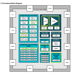
We are considering a solution that uses the TPLD1201 to sense the coil current and perform current feedback control.

The inputs to the TPLD1201 are the current command value (analog) and current feedback (analog).

The output of the TPLD1201 is planned to be an output (2 or 4 outputs) that controls the H-bridge with PWM, and we would also like to adjust the gain of the PI regulator.

Could you comment on the feasibility of this?

Thanks,

Conor

  • Hi Conor,

    It's tough to visualize this from your description. How many different PWM levels do you see yourself needing? The TPLD1202 has a built in PWM generator, but for TPLD1201 it would need to be built from the logic blocks in the TPLD1201, which is possible but may limit the achievable resolution.

    How is the gain of the PI regulator controlled?

    Looking at this, my first thought is it is likely feasible, but moving to TPLD1202 may make the design easier and improve the end performance.

    Best,

    Ian

  • Hi Ian,

    It's tough to visualize this from your description. How many different PWM levels do you see yourself needing? The TPLD1202 has a built in PWM generator, but for TPLD1201 it would need to be built from the logic blocks in the TPLD1201, which is possible but may limit the achievable resolution.

    What level of resolution can be achieved when using the built-in PWM generator of the TPLD1202? Also, in the case of the TPLD1201, what is the maximum resolution that can be achieved when generating PWM using a logic block? Also, how many PWM outputs does the TPLD1201 and TPLD1202 have? I am considering generating a PWM signal (2 or 4 outputs) to control an H-bridge circuit.

    How is the gain of the PI regulator controlled?

    I would like to be able to adjust the PI regulator gain (Kp: proportional gain, Ki: integral gain) to an optimal value after the system starts up.

    Do you have any advice on how to build and implement the internal block?

    Looking at this, my first thought is it is likely feasible, but moving to TPLD1202 may make the design easier and improve the end performance.

    It seems that the datasheet of TPLD1202 has not been disclosed. I have applied for a detailed data sheet, but it seems that I have not yet received permission.

    Let me summarize what I want to achieve again. I am considering using TI's INA series to sense the coil current and input it to the PLD as a feedback signal.

    ■Expected configuration
    ・Input signal (input to PLD):
     - Current command value (analog)
     - Current feedback value (analog)
    *These analog signals will be converted to digital signals via an A/D converter (ADC) and then input to the PLD, right?

    ・Output signal (H-bridge drive):
     - Generate PWM signals (2 or 4 outputs) to control the H-bridge circuit

    Control flow
    1. Sense the coil current with the INA series
    2. Input the current command value and feedback value to the PLD via A/D conversion
    3. Configure a PI regulator inside the PLD and perform current feedback control
    4. Generate a PWM signal based on the output of the PI regulator to drive the H-bridge

    Thanks,

    Conor

  • Hi Connor,

    The TPLD1202 has 4 built in PWM modules, each with a resolution of about 0.4% of a duty cycle. You could set up the feedback loop using the integrated analog comparators to measure the feedback voltages and use logic to control if the PWM increases or decreases based on those inputs.

    When you say you want 2 to 4 PWM outputs, are those the same signal or would you also need 4 PWM generators? The outputs of the TPLD1201 and TPLD1202 are all GPIOs. Neither has dedicated PWM outputs, but the outputs are all configurable so any of them could be set as the PWM output.

    I'm not familiar with a PI regulator, but this device is not rated for linear mode, so we don't recommend using it for a gain stage.

    Best,

    Ian

  • Hi Ian,

    If you have any application notes or reference information that performs similar control, please share them with me!

    When you say you want 2 to 4 PWM outputs, are those the same signal or would you also need 4 PWM generators?

    From your answer, is it correct to assume that since there are four PWM generators, it can control four different signals?

    I'm not familiar with a PI regulator, but this device is not rated for linear mode, so we don't recommend using it for a gain stage.

    Based on my research, I would like your comments on the feasibility and concerns of 1 to 3.

    As for the construction of a PI regulator using current feedback, I think that it is possible to construct a PI regulator using current feedback with TPLD1202 by designing proportional and integral control using LUT and counter functions and applying it to H-bridge control with PWM output.

    A specific example is the following steps 1 to 3.

    1. Obtaining feedback of current value
    Detect the current value using an INA series current sense amplifier or similar and input it as an analog signal to the TPLD's analog comparator (ACMP).
    The analog comparator compares the target current value (reference voltage) with the actual current value to generate the deviation e(t).

    2. How to implement PI control
    Construct a digital PI regulator using the TPLD's lookup table (LUT) and counter/delay functions.
    ■ Proportional (P control)
    -Define the output proportional to the deviation e(t) using the LUT.
    -The proportional gain K p can be set by adjusting the table value of the LUT.

    ■ Integration (I control)
    The deviation e(t) is integrated over time using the counter/delay function.
    The integration result is processed by the LUT and the integral gain K i is set.

    ■ Output synthesis
    To add the output of the P control and I control, the LUT or GPIO output is set appropriately.

    3. H-bridge PWM control
    The output of the PI control is converted to a PWM waveform using the PWM generation function of the TPLD1201 and fed back to the H-bridge circuit.
    The PWM frequency and duty cycle are dynamically adjusted according to the output of the PI regulator.

    Thanks,

    Conor

  • Hi Hi Ian,

    Do you have any update?

    Thanks,

    Conor

  • Hi Conor,

    Yes, each PWM generator can control a different signal.

    This application definitely sounds do-able in TPLD1202, but we don't have an app note on that yet as this part has not been fully released.

    Best,

    Ian

  • Hi Ian,

    The image is an internal block diagram of the TPLD1202. Is it possible to achieve current feedback control by using the block functions circled in yellow? Detailed verification is required.

    You say that PI control is possible, but do you intend to achieve gain adjustment using an LUT block? Or do you intend to adjust the gain value and reference value externally via I2C/SPI?

    Thanks,

    Conor

  • Hi Connor,

    If you have a goal voltage in mind, you can use the PWM generator to control the H-bridge circuit and feedback the voltage through the analog comparator. The analog comparator can then control the PWM generator and instruct it to increase or decrease the duty cycle of the signal to bring the H-bridge output voltage into compliance. This would use the PWM generator, analog comparators, and LUTs.

    I'm not sure where PI control comes into this. As I said, I'm not familiar with this. If you are trying to control the output voltage of the H-bridge circuit by controlling the reference voltage of the analog comparators, that is not possible on TPLD1202.

    Best,

    Ian

  • Hi Ian,

    I'm not sure where PI control comes into this. As I said, I'm not familiar with this. If you are trying to control the output voltage of the H-bridge circuit by controlling the reference voltage of the analog comparators, that is not possible on TPLD1202.

    I'm sorry, but I need to know more about whether this is possible. Would it be possible to discuss this within the support team?

    I think that it is possible to adjust the gain of the PI regulator by using the TPLD1202.

    ★Blocks used

    -Analog Comparator (ACMP): Generates an error signal (the difference between the target value and the feedback value).

    -LUT (Lookup Table): Applies proportional gain (K p ).

    -Counter/digital filter: Realizes integral action and applies integral gain (K i ).

    -PWM generator: Generates an output PWM signal based on a control signal.

    ■How to adjust proportional gain (K p )

    Realizing proportional gain using LUT

    The error signal is used as input, and an output is generated by multiplying it by a proportional coefficient using the LUT. The output of the LUT is directly reflected in the PWM duty ratio.

    ◯Example: Error signal × Proportional gain
     - Input: Error signal (e.g. 0 to 1)
     -LUT setting: Multiply by proportional gain K p = 2.0.
     -Output: 0.5 × 2.0 = 1.0 (duty ratio)

    ■How to adjust integral gain (K i)
    Integral operation using a counter
    Integrate the error signal using a counter.
    Generate a value by multiplying the counter output by integral gain K i.

    Example: Integral calculation
     - Input: Error signal (function of time)
     - Counter: Sample the error signal at regular intervals and calculate the cumulative value.
     - Output: Counter value × integral gain K i.

    Question 1
    Is it possible to use it as above?
    From reading the datasheet, each block seems to meet the requirements, but I would like your comments.

    Question 2
    In addition to setting the dynamic gain adjustment K p as a fixed value, can it also be dynamically changed externally via I2C/SPI?

    Question 3
    Is it possible to change the integral response by adjusting the counter sampling period or increase rate through adjustment of integral control response?

    Thanks,

    Conor

  • Hi Conor,

    The analog comparator outputs a logical high if the v+ input is higher than the v- input. It is not a proportional signal to the difference between the inputs.

    It sounds like you are trying to have the logical elements in the TPLD function in linear mode, which is not supported. These are strictly logical elements.

    The best method of controlling the PWM generators in the TPLD1202 is by either using a feedback loop through the HBridge and the analog comparators to logically control whether the duty cycle increments up, down, or stays the same, or to use 12C or SPI to directly control the duty cycle of the PWM generator.

    Best, Ian