This thread has been locked.

If you have a related question, please click the "Ask a related question" button in the top right corner. The newly created question will be automatically linked to this question.

AM620-Q1: Could we keep GPIO status after AM62 swap into "deep sleep mode" or "partial I/O mode"?

Part Number: AM620-Q1
Other Parts Discussed in Thread: SK-AM62-LP

Tool/software:

Hi, Dear Expert

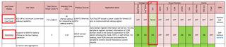
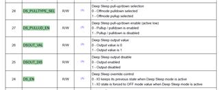
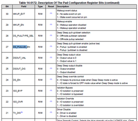
As title description, customer wants to keep "last I/O status" after SoC swap into "deep sleep" or "partial I/O" mode.

for example, gpio0_49 = low is in "normal active mode", and then we hope gpio0_49 "keep low" when SoC swap into "deep sleep" or "partial I/O" mode.

Is it possible?

or Could we set each GPIO status when SOC (AM62) swap into "deep sleep" or "partial I/O" mode?

Thank you very much

Gibbs

  • Hello Gibbs,

    What OS is the customer planning on using? This will help us determine the right expert to support this inquiry.

    -Daolin

  • We found that when GPIO has no pull-up or pull-down resistor, when it enters Deep Sleep mode, GPIO can remain as pull-up (1.8V) or pull-down (0V), but when there is a pull-up resistor, set GPIO to pull-down output, and the output of GPIO in working mode is 1.8V, after entering Deep Sleep mode, the voltage of GPIO becomes 1.2V, and when there is a pull-down resistor, set GPIO to up-output, and normal mode is 0V, Deep The GPIO voltage in Sleelp mode becomes 1.2V, does the GPIO output become weaker after entering Deep Sleep mode?

  • Hello,

    Just to be clear, a GPIO cannot be changed during Deep Sleep or Partial I/O. One of the steps in the suspend sequence is to save the IO context, then restore the context during the wakeup sequence. This means a GPIO must be set prior to entering a suspend state, then it will be maintained during the suspend sequence.


    GPIO voltage tends to slightly change when entering sleep from prior experiments (3.3V in Active -> 3.28V in Deep Sleep). Its possible to utilized the internal pull resistor to maintain the existing state. Refer to 14.2.1.2 Pad Configuration Registers in the AM62x TRM: https://www.ti.com/lit/ug/spruiv7b/spruiv7b.pdf

    You can write to the register using devmem2 to test the toggle of the internal pull resistor while in suspend state. You can also look into FORCE_DS_EN to see which IO state should be utilized when entering a suspend state.

    Best Regards,

    Anshu

  • I tried to set the GPIO to DevMEM2 0x000F40C4 W 0x00018007/0x01018007 before entering Deep Sleep mode, and pulled down the GPIO output, the voltage of GPIO before entering Deep Sleep was 0V, but after entering Deep Sleep, because of the presence of an external 1.8V pull-up resistor, the voltage of GPIO changed to 1.2V again, and it didn't seem to have any effect,Please help see if there are other solutions

  • Hi, Anshu

    Need your Update. If I say something wrong, please correct me.

    Thank You!

    Here are my comments.

    Hi, 

    I think you may also check "FORCE_DS_EN" bit, not only "DS_EN" bit.

    DevMEM2 0x000F40C4 W 0x00018007/0x01018007 

    Ref. TRM p5818.

    For example, I think (guess) ,

    FORCE_DS_EN = 1

    DS_EN = 0

    DSOUT_VAL = 0 (if we need set to 0)

    DS_PULLUD_EN = 0

    DS_PULLTYPE_SEL = 0

    By the way, I found a good tips for you studying

    Ref.

    https://e2e.ti.com/support/processors-group/processors/f/processors-forum/1078518/dra821u-j7200?ReplyFilter=Answers&ReplySortBy=Answers&ReplySortOrder=Descending

    https://www.ti.com/lit/ug/spruiu1d/spruiu1d.pdf?ts=1736745878006&ref_url=https%253A%252F%252Fwww.ti.com%252Fproduct%252FDRA821U%253FkeyMatch%253Ddra8%2526tisearch%253Duniversal_search%2526usecase%253Dpartmatches

    -->p681, CTRLMMR_WKUP_PADCONFIG54

    This debug experience should be very similar AM62x

    Pls record your test steps like this thread.

    Thanks

    Gibbs

  • Hi Gibbs,

    Apologies for the delay as I was returning from holiday. I've seen others ask about keeping a GPIO pulled high, but not low. I'm working on replicating the issue so please allow some time to continue debugging this and expect an update by Friday this week.

    Thanks,

    Anshu

  • Hi Gibbs,

    Here's exactly what I did:

    • Hardware: SK-AM62-LP
    • Software: Linux SDK 10.0

    In the Linux device tree, I assigned enabled two GPIOs:

    &main_pmx0 {
        main_gpio0_pins_default: main-gpio0-default-pins {
    		pinctrl-single,pins = <
    		    AM62X_IOPAD(0x009c, PIN_INPUT, 7) /* (V25) GPMC0_WAIT1.GPIO0_38 */
    		    AM62X_IOPAD(0x00ac, PIN_INPUT, 7) /* (L21) GPMC0_CSn1.GPIO0_42 */
    		>;
    	};
    };
    
    &main_gpio0 {
    	status = "okay";
    	pinctrl-names = "default";
    	pinctrl-0 = <&main_gpio0_pins_default>;
    	gpio-line-names = "", "", "", "", "", "", "", "", "", "", // main_gpio0_0 -> 9
    						"", "", "", "", "", "", "", "", "", "", // main_gpio0_10 -> 19
    						"", "", "", "", "", "", "", "", "", "", // main_gpio0_20 -> 29
    						"", "", "", "", "", "", "", "", "MG038", "", // main_gpio0_30 -> 39
    						"", "", "MG042", "", "", "", "", "", "", ""; // main_gpio0_40 -> 49
    };

    Both of these GPIOs don't have any external pull resistors as shown in the SK-AM62-LP schematic:

    In the EVM's Linux Command Line, I set both GPIOs to low:

    root@am62xx-lp-evm:~# gpioset MG038=0
    root@am62xx-lp-evm:~# gpioset MG042=0

    Here is the PADCONFIG register value:

    I changed one of the GPIO's PADCONFIG register to enable the internal pull down resistor by changing BIT16 (0x00050007 -> 0x00040007). There are no other changes.

    root@am62xx-lp-evm:~# cat /sys/kernel/debug/pinctrl/f4000.pinctrl-pinctrl-single/pingroups
    ...
    group: main-gpio0-default-pins
    pin 39 (PIN39)
    pin 43 (PIN43)
    ...
    
    root@am62xx-lp-evm:~# cat /sys/kernel/debug/pinctrl/f4000.pinctrl-pinctrl-single/pinmux-pins | grep main-gpio0
    pin 39 (PIN39): 600000.gpio (GPIO UNCLAIMED) function main-gpio0-default-pins group main-gpio0-default-pins
    pin 43 (PIN43): 600000.gpio (GPIO UNCLAIMED) function main-gpio0-default-pins group main-gpio0-default-pins
    
    root@am62xx-lp-evm:~# cat /sys/kernel/debug/pinctrl/f4000.pinctrl-pinctrl-single/pins | grep 'pin 39'
    pin 39 (PIN39) 38:600000.gpio f409c 00050007 pinctrl-single 
    root@am62xx-lp-evm:~# cat /sys/kernel/debug/pinctrl/f4000.pinctrl-pinctrl-single/pins | grep 'pin 43'
    pin 43 (PIN43) 42:600000.gpio f40ac 00040007 pinctrl-single 
    root@am62xx-lp-evm:~# 
    

    I measured the voltage of the GPIO before, enter, and exiting Deep Sleep.

    For the GPIO without the internal pull down resistor, there was a slight increase of the GPIO voltage upon wake up. This peak was 136mV.

    For the GPIO with the internal pull down resistor was added, there was no change in the GPIO voltage when waking up from deep sleep.

    If you enable the internal pull down resistor by changing Bit 16 of the PADCONFIG register, there should be no change in the voltage assuming there is no pull resistor on the pin.

    Best Regards,

    Anshu

  • Hi, Anshu

    Thank you very much for your detail test result

    let us studying.

    Gibbs

  • Hi Gibbs

         I tried DevMEM2 0x000F40C4 W 0x00018007/0x01018007 as you said, and then set the gpio to low, went into deep sleep mode, because there was a pull-up resistor of 1.8v externally, so it was still able to output 1.2v, the phenomenon did not change


  • Hi, 

    (1) Recommend you duplicate Anshu's test on EVB (SK-AM62-LP) "first", because we need to make sure you have correct SW setting concept

    (2) And then, post your schematic about "GPIO0_49" part which may include related PU/PD resistor/ or related device which connect to this gpio. 

    (3) By the way, please dump your pinmux setting for "GPIO0_49". (devmem2 0x000F40C4)

    (4) If it possible, try to un-connect another device or w/o PU/PD resistor, direct measure the pin out.

    (5) By the way, Base on Anshu's test, I found the value should be 0x0005007 or 0x0004007

    Gibbs

  • Hi gibbs

         This is gpio0_49 with the circuit diagram

    If we remove the pull-up resistor on the outside, GPIO can pull low in Deep Sleep mode, but with a pull-up resistor on the outside, the voltage can only be changed to 1.2V

  • Hi, n

    How about use 0x0005007 or 0x0004007?

    Gibbs

  • Hi xiao-an,

    Let us know when you replicate this on a TI EVM. The GPIO will be influenced by an external pull up/down resistor.

    Best,

    Anshu

  • Hi Anshu:

            I tested the scl pin as shown in the picture, modified it to the gpio pin mode devmem2 0x000F40B0 w 0x00010007/0x01018007/0x00040007/0x0005007, and then set it to low voltage, measured voltage R30 before entering sleep with voltage of 3.3v at both ends, and after entering deep sleep, R30 with voltage of 3.3v and 2.7v at both ends respectively.

  • Hi xiao-an,

    Please let me know if my understanding of the issue is correct.

    You are trying to keep the GPIO voltage low (~0V) while the SoC is in Deep Sleep and Partial I/O, but you have an external pull up resistor connected to the GPIO.

    Once you confirm this, we can continue debugging this issue.

    Thanks,

    Anshu

  • Hi 

    Your understanding is right

  • Hi xiao-an,

    Thanks for confirm.

    One concern is an external pull up resistor might cause the GPIO value to slightly change since I don't think the internal pull down resistor would be strong enough keep the voltage down and the voltages would be conflicting.

    Explain how the GPIO is set to low. Is this through user space or another way? Share any device tree changes regarding the GPIO.

    Best Regards,

    Anshu

  • Hi Anshu:

          First, set the tree pair to use the GPIO configuration as follows:AM62X_IOPAD(0x0d8, PIN_OUTPUT, 7),Then use gpioset -z -c gpiochip0 19=0 at the application layer,Measure the GPIO voltage before and after entering Deep Sleep(The register address and GPIO are only examples and do not represent the actual use of the GPIO).

  • Hi Anshu,

          The version we are using is 10.0.007, I see that version 10.01.10 has a fix for the problem that GPIO cannot be kept, please is it related to this one of ours.

  • Hi xiao-an,

    There were a few changes to the drivers, you are welcomed to try the new SDK for this.

    Thanks,

    Anshu

  • Hi Anshu,

           ti is there a relevant path that can be provided for us to fix this.

    thanks.

  • Hi  Anshu, 

       We tried to do the test with TI's latest SDK on the EVB version, and the problem is still not solved.

    Set DevMEM2 0x000F40B0 W 0x00010007 before entering Deep Sleep mode, then use GPIOSET to set the gpio0_43 low, and then enter Deep Sleep mode, measuring the voltage of the R30 segment to 2.7V.It looks like when there is an external pull-up resistor, it still can't be pulled low in deep sleep mode。

    The measurement PMIC_LPM_EN0 pin also does not indicate whether the AM62X has entered Deep Sleep mode。

  • Hi Xaio-an,

    I will loop in the hardware team to help with the schematic side. Please allow some time for a response.

    Thanks,

    Anshu

  • Hi Xaio-an,

    I am not sure what i need to review, could you please point.

    regards,

    Sreenivasa

  • Hi, Sreenivasa

    Let's me summarize our discussion,

    Our Goal :

    We set gpio (ex:main domain gpio0_43/42/38) output low, and we hope gpio0_43 "keep low" when AM62 go into deep mode. 

    Experiments 1

    We found gpio0_43 can keep low when AM62 in deep sleep, but it need to base on gpio0_43 floating W/O PU resistor

    Experiments 2

    We found gpio0_43 can not keep low when AM62 in deep sleep, because gpio0_43 have an extern PU resistor (4.7k/10k) to 3.3V. we measure gpio0_43 "return" to 2.7v in deep sleep mode.

    Here are some question,

    (1) Base on our appication goal, What's correct pinmux setting for gpio0_43?

    We already try these values, but it does not work

    --> 0x00010007/0x01018007/0x00040007/0x0005007

    (2) Does it mean our "internal" PD resistor is not strong enough?

    (3) Base on our application goal, Do we have any suggestion for schematic design with gpio0_43?

    we hope gpio0_43 always keep low in deep sleep mode.

    Thank You

    Gibbs

  • Hello Gibbs, 

    I need to check internally.

    I suspect we need to use Bit 27 and Bot 28 and DNI external resistor. I will confirm.with the team.

    Regards,

    Sreenivasa 

  • Hello Gibbs

    Experiments 2

    We found gpio0_43 can not keep low when AM62 in deep sleep, because gpio0_43 have an extern PU resistor (4.7k/10k) to 3.3V. we measure gpio0_43 "return" to 2.7v in deep sleep mode.

    The internal pul value is around 50K nominla.

    This indicated there is a pulldown and pullup enabled

    RPU Pull-up Resistor 40 50 60 kΩ
    RPD Pull-down Resistor 40 50 60 kΩ

    You might want to review Bit 24..28 of the pad config register to ensure there is no pulldown enabled and verify.

    Regards,

    Sreenivasa

  • Hi, Sreenivasa & Anshu

    Thanks you replies

    I have two question,

    [Question 1] Which one is correct PU/PD internal Resistor?

    I notice Resistor with three values (40/50/60/kΩ), which one is correct PU/PD resistor?

    [Question 2] What's correct bit setting for Bit 24~28?

    Because I try to identify this is an hardware or software issues, so I need to lock software setting first.

    Here are my test w/ PU resistor(10/kΩ) on GPIO0_38 for AM62_LP_EVM

    I need your suggestion, because I want to know what's correct setting (PADCONFIG) look like?

    Should we also increase (or decrease) external PU Resistor to solve this problem?

    PADCONFIG = 0x0001 0007
    I measure  GPIO0_38 = 2.7v in DS mode, even we set GPIO0_38 = 0v before enter DS mode
    bit 28, DS_PULLTYPE_SEL = 0, OFF MODE PULLDOWN SELECTED
    bit 27, DS_PULLUD_EN = 0, PU/PD is enabled
    bit 26, DSOUT_VAL = 0, output value = 0
    bit 25, DSOUT_DIS = 0, output enable
    bit 24, DS_EN = 0, I/O keep previous state when deep sleep mode active

    PADCONFIG =0x0201 0007
    I measure  GPIO0_38 = 2.7v in DS mode, even we set GPIO0_38 = 0v before enter DS mode
    bit 28, DS_PULLTYPE_SEL = 0, OFF MODE PULLDOWN SELECTED
    bit 27, DS_PULLUD_EN = 0, PU/PD is enabled
    bit 26, DSOUT_VAL = 0, output value = 0
    bit 25, DSOUT_DIS = 1, output disable
    bit 24, DS_EN = 0, I/O keep previous state when deep sleep mode active

    PADCONFIG =0x0004 0007
    I measure  GPIO0_38 = 2.7v in DS mode, even we set GPIO0_38 = 0v before enter DS mode
    bit 28, DS_PULLTYPE_SEL = 0, OFF MODE PULLDOWN SELECTED
    bit 27, DS_PULLUD_EN = 0, PU/PD is enabled
    bit 26, DSOUT_VAL = 0, output value = 0
    bit 25, DSOUT_DIS = 0, output enable
    bit 24, DS_EN = 0, I/O keep previous state when deep sleep mode active
    bit 18, RXACTIVE, enable

    PADCONFIG =0x0001 0087
    I measure  GPIO0_38 = 2.7v in DS mode, even we set GPIO0_38 = 0v before enter DS mode
    bit 28, DS_PULLTYPE_SEL = 0, OFF MODE PULLDOWN SELECTED
    bit 27, DS_PULLUD_EN = 0, PU/PD is enabled
    bit 26, DSOUT_VAL = 0, output value = 0
    bit 25, DSOUT_DIS = 0, output enable
    bit 24, DS_EN = 0, I/O keep previous state when deep sleep mode active
    bit 15, FORCE_DS_EN = 1, Ative deep sleep pad control, override DMSC0


    Thank you very much

    Gibbs

  • Hello Gibbs

    Thank you.

    [Question 1] Which one is correct PU/PD internal Resistor?

    I notice Resistor with three values (40/50/60/kΩ), which one is correct PU/PD resistor?

    Please refer data sheet.

    Internal pulls have a wide range.

    Regards,

    Sreenivasa

  • Update,

    Base on LVCMOS, different  VDD_IO voltage has different PU/PD Resistor values

    Gibbs

  • Hello Gibbs, 

    Thank you. 

    Base on LVCMOS, different  VDD_IO voltage has different PU/PD Resistor values

    Please refer below. Not sure what you meant by the above statement.

    7.8.6 LVCMOS Electrical Characteristics

    1.8-V MODE

    RPU Pull-up Resistor 15 22 30 kΩ
    RPD Pull-down Resistor 15 22 30 kΩ

    3.3-V MODE

    RPU Pull-up Resistor 15 22 30 kΩ
    RPD Pull-down Resistor 15 22 30 kΩ

    Regards,

    Sreenivasa

  • Hi Gibbs,

    Changing Bits 24:28 will only matter is Bit15=1.

    Best Regards,

    Anshu

  • Hi, Anshu

    Let's me check some thing.

    (1) We just need to "care about" Bits 24:28 and let Bit15=1, isn't?

    (2)Should we let this pin become "input"? Because I hear some information, internal PU/PD only activity in GPIO "input mode", isn't?

    So I guess correct setting could be  PADCONFIG =0x0004 8007

    bit 28, DS Pull down enable

    bit 27, DS_PULLUD_EN = 0, PU/PD is enabled in DS mode
    bit 26, DSOUT_VAL = 0, output value = 0
    bit 25, DSOUT_DIS = 0, output enable
    bit 24, DS_EN = 0, I/O keep previous state when deep sleep mode active
    bit 15, FORCE_DS_EN = 1, Ative deep sleep pad control, override DMSC0

    bit 18 =1, input mode (RX)

    But we also need to care about internal PD resistor about 15~30kΩ, so customer may need to increase "external " PU resistor if they want status keep in low in DS mode.

    Thanks

    Gibbs

  • Hi Gibbs,

    Bit 18 enables/disables the input buffer for the pad. This means setting the bit high will allow for the pad to be capable of receiving data.

    But we also need to care about internal PD resistor about 15~30kΩ, so customer may need to increase "external " PU resistor if they want status keep in low in DS mode.

    I'll loop in the hardware team for this query.

    Best Regards,

    Anshu

  • Hi All,

    As i understand if the interest is to maintain a known state in deepsleep, the internal pulls should support and there may not be a need for external oull. 

    Regards,

    Sreenivasa

  • Close this thread

    Customer Add PU 100k resistor to solve this problem.

    Gibbs

  • Hello Gibbs

    Thank you for the input.

    Regards,

    Sreenivasa

  • Hello Gibbs

    Customer Add PU 100k resistor to solve this problem.

    The 100K pullup may be a concern given the LVCMOS IO leakage.

    Refer below section of the FAQ:

    Additional inputs on selecting pulls (pullup or pulldown) for LVCMOS IOS

    https://e2e.ti.com/support/processors-group/processors/f/processors-forum/1386586/faq-am62x-am64x-am243x-custom-board-hardware-design-how-to-handle-used-unused-pins-peripherals-e-g-gpios-serdes-usb-csi-mmc-emmc-sd-card-csi-oldi-dsi-cap_vddsx

    Regards,

    Sreenivasa