This thread has been locked.

If you have a related question, please click the "Ask a related question" button in the top right corner. The newly created question will be automatically linked to this question.

TDA4VM: Summary of problems encountered during the first tuning of isp

Part Number: TDA4VM


Tool/software:

HI 

   This is my first time to tuning isp, I may encounter many problems, I hope you can help me, or is there isp training, can I participate in it


问题分类	                            
[sensor]_properties.txt configuration	
1. line_mode与WDR_mode的定义及选择条件?
2. WDR_BIT_DEPTH: 一般是20 or 24 应该怎么选择?
3. WDR_KNEE_X/WDR_KNEE_Y的定义及怎么填写?
4. BLACK_PRE/BLACK_POST的定义及怎么填写?
5. H3A_INPUT_LSB的定义及怎么填写?
	
Black Level Correction	                
1. 目前操作方法是用手捂住镜头,捕获raw图像,请问这种操作对吗?或是需要在什么条件下的暗箱进行操作?
2. 需要捕获多个曝光增益下的图片测试吗?
	
H3A	                                    
1. 根据文档描述,定焦摄像头不需要多余的H3A步骤,请问AWB及AE也不需要调试吗?
	
CFA+WDR	                                
1. 根据文档描述,此软件只支持RGGB 及 RCCB ,请问可以支持BGGR格式吗?
2. CFA的选项卡中各项说明?是否只需选择默认值?
3. WDR和GLBCE的选项卡中各项说明及如何填写?
	
AWB	                                    
1. 如果图像采用压缩型宽动态范围(WDR)格式,需要一个分段线性(PWL)拐点文件,如何获得PWL文件?
2. Choose Flash Setting/Max Horizontal Paxels/Max Vertical Paxels/WDR Gamma % in RAWFE (100*G)的定义及怎么填写?
	
Color Correction	                    
1. 如何获得伽马对比度查找表?
	
EE	                                    
1. 从文档中不太理解边缘增强的三块区域具体应该怎么调试,需要此模块调试的具体讲解
	
LDC	                                    
1. 如何获得LDC LUT file?
2. LDC的调试参数应该按什么标准填写?
	
LSC	                                    
1. 如何获得LSC Input Table?
	
GAMMA	                                
1. Gamma LUT一般是选择标准的还是用户自定义的?如果是用户自定义的,这个表怎么获得?
	
DPC	                                    
1. 缺陷像素校正参数如何修改?

Thank you very much and look forward to your reply!

  • Hello,

    Most of the team members are out of office. Please expect delayed response.

    - Keerthy

  • Hi,

    It looks like you might have limited experience with raw image sensors.
    You may take a look at the links below first for some background information.

    https://www.ti.com/lit/pdf/sprad86

    https://www.ti.com/lit/pdf/spracu7

    https://e2e.ti.com/support/processors-group/processors/f/processors-forum/1058565/faq-tda4vm-how-to-create-a-ldc-mesh-lut-for-fisheye-distortion-correction-on-tda4?keyMatch=LDC%20FAQ

    https://e2e.ti.com/support/processors-group/processors/f/processors-forum/1275034/faq-default-dcc-profile-generation-tool-for-tda4-am6xa-isp-vpac?tisearch=e2e-sitesearch&keymatch=%20user%3A35541

    https://e2e.ti.com/support/processors-group/processors/f/processors-forum/1405138/faq-tda4vm-how-to-create-lens-shading-correction-lut-for-vpac-viss-lsc

    https://e2e.ti.com/support/processors-group/processors/f/processors-forum/1261451/faq-dcc-tuning-tool-v3-1-for-vpac-on-tda4x-and-am6xa-devices

    https://e2e.ti.com/support/processors-group/processors/f/processors-forum/1262114/faq-setting-up-auto-exposure-ae-for-your-image-sensor-with-tda4-am6xa-isp-vpac

    It would be helpful for you to speak with a local FAE from TI and your sensor vendor if possible for some basics.

    >> [sensor]_properties.txt configuration

    Please refer to sample configurations in the link below.

    https://git.ti.com/cgit/processor-sdk/imaging/tree/tools/default_DCC_profile_gen/configs?h=main

    >> Black Level Correction

    If you know the pedestal in your sensor driver, you may fill it in in the configuration file above.

    >> H3A

    AF is not needed for fixed focal lens, and AE/AWB are necessary in most cases.

  • Hi,

    I'm using the edge AI - 09_02_00_05 version of the SDK. As you mentioned, generating the LDC LUT and LSC LUT  requires Matlab scripts. But I have no idea where to find these scripts.

    Besides, I've also downloaded the PROCESSOR_SDK_VISION_03_08_00_00.bin. However, I'm not clear about what the function of this SDK is and whether it will be useful for me or not.
    Thanks!
  • Hi,

    Happy New Year!

    Sorry, I am not able to see your user name properly as it shows up as "? ?".

    generating the LDC LUT and LSC LUT  requires Matlab scripts. But I have no idea where to find these scripts.

    They are in the e2e FAQ for LDC and LSC.

    https://e2e.ti.com/support/processors-group/processors/f/processors-forum/1058565/faq-tda4vm-how-to-create-a-ldc-mesh-lut-for-fisheye-distortion-correction-on-tda4?keyMatch=LDC%20FAQ

    https://e2e.ti.com/support/processors-group/processors/f/processors-forum/1405138/faq-tda4vm-how-to-create-lens-shading-correction-lut-for-vpac-viss-lsc

    Besides, I've also downloaded the PROCESSOR_SDK_VISION_03_08_00_00.bin. However, I'm not clear about what the function of this SDK is and whether it will be useful for me or not.

    That one you downloaded is for TDA3 rather than TDA4.
    I am not sure why you are referring to it.

    This link below is for TDA4VM (J721e).

    www.ti.com/.../PROCESSOR-SDK-J721E

    Which TDA4 EVM and OS are you working on?

  • Hi,

    Happy New Year! I just changed the name in my personal information. Haha.

    I'm using the TDA4VM (J721e), and I currently have three questions.

    1.I have a fixed - focus camera and don't need to debug the autofocus (AF). However, if I need to tune the AWB and AE, how should some of the V and H parameters in H3A be configured? Or rather, if there's no need to adjust the autofocus (AF), then the entire H3A module doesn't need to be tuned.

    2.In the Color Correction module, how can the gamma - contrast lookup table be obtained?

    Thanks.

  • Hi Ying,

    if I need to tune the AWB and AE, how should some of the V and H parameters in H3A be configured?

    You may start with the default settings coming from the python script.

    https://e2e.ti.com/support/processors-group/processors/f/processors-forum/1275034/faq-default-dcc-profile-generation-tool-for-tda4-am6xa-isp-vpac?tisearch=e2e-sitesearch&keymatch=%20user%3A35541

    If you are happy with the AE/AWB performance, you don't need to change it further.

    I have a fixed - focus camera and don't need to debug the autofocus (AF).

    AF is not needed in this case.

    2.In the Color Correction module, how can the gamma - contrast lookup table be obtained?

    You may leave it empty.
    It is optional.

  • Hi,

    Thanks for the help.

    1.The video stream taken by my camera is mirrored. What is the reason for this? Is it the problem of the camera register configuration.

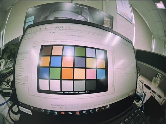
    2.Since the lens is a convex lens, DCC may not be accurate in identifying the color blocks of the XRite Color Checker chart. Does this affect the debugging.

    3.In general,the value of H3A_INPUT_LSB should be filled in.

    Thanks.

  • Hi Ying,

    1.The video stream taken by my camera is mirrored. What is the reason for this? Is it the problem of the camera register configuration.

    It is mostly due to the way sensor is mounted on the PCB.

    2.Since the lens is a convex lens, DCC may not be accurate in identifying the color blocks of the XRite Color Checker chart.

    You may keep the color checker at the center of FOV to reduce lens distortion.

    3.In general,the value of H3A_INPUT_LSB should be filled in.

    You may check the refer to sample settings for other sensors.

    https://git.ti.com/cgit/processor-sdk/imaging/tree/tools/default_DCC_profile_gen/configs?h=main

  • Hi Gang,

    I have a few more basic questions to ask you. My sensor is ox03c10.

    1. Do you have the relevant configurations about ox03c10_properties.txt. If anything, that would be great.

    2. If not, Could you tell me how to fill in WDR decompanding knee points, I can't understand clearly what is stated in the datasheet.

    3. Could you help me check that my ox03c10_properties.txt file is correct?

    SENSOR_WIDTH 1920
    SENSOR_HEIGHT 1280
    
    # 0=RGGB;  1=GRBG;  2=GBRG;  3=BGGR,  4=MONO,
    #10=RGGI, 11=GRIG, 12=BGGI, 13=GBIG, 14=GIRG, 15=IGGR, 16=GIBG, 17=IGGB
    COLOR_PATTERN 3
    
    # sensor mode: 0 for linear (no decompanding), 1 for WDR (decompanding)
    WDR_MODE 0
    
    # raw sensor image BIT_DEPTH: it may be 8, 10, or 12 for linear sensors; typically 12 for WDR mode because of companding
    BIT_DEPTH 12
    
    # WDR BIT_DEPTH: WDR raw sensor image bitdepth after decompanding, typically 20 or 24
    WDR_BIT_DEPTH 24
    
    # WDR decompanding knee points (comma separated without spaces in between)
    WDR_KNEE_X 0,512,1408,2176,4095,65535
    WDR_KNEE_Y 0,2048,16384,65536,1048063,1048063
    
    # Sensor black level to subtract before decompanding (for some Sony WDR sensors)
    # When PCID is on for RGBIR sensors, black level might be set to 0
    BLACK_PRE  0
    
    # Sensor black level to subtract after decompanding (for most WDR sensors and all linear sensors)
    # When PCID is on for RGBIR sensors, black level might be set to 0
    BLACK_POST  0
    
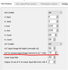
    # GAMMA value for compressing 20/24-bit WDR raw to 16-bit ISP internal
    # typically around 50 (0.5) for 24-bit WDR sensors and 70 (0.7) for 20-bit sensors
    GAMMA_PRE 60
    
    # LSB location for H3A input bit range (from bit-H3A_INPUT_LSB to bit-H3A_INPUT_LSB+9) 
    H3A_INPUT_LSB 2

    I would appreciate it very much.

  • Hi Gang,

    This is my image effect.

  • Hi Ying,

    1. Do you have the relevant configurations about ox03c10_properties.txt. If anything, that would be great.

    We have not worked on any X3C cameras.

    2. If not, Could you tell me how to fill in WDR decompanding knee points, I can't understand clearly what is stated in the datasheet.

    The knee points are defined in your X3C sensor driver and sensor datasheet.
    That is NDA information for X3C, you would have to check with OVT directly.

    3. Could you help me check that my ox03c10_properties.txt file is correct?

    Looks ok to me.

  • This is my image effect.

    This looks reasonable to me as well.
    If you get decompanding knee points correctly, the color could be better.

  • Hi Gang,

    1. I am learning to generate LDC LUT, what do these parameters mean?pitch_in_mm = 0.0028; f_in_mm = 0.85.

    2. I asked The lens manufacturer and they said they didn't have The lens shading spec file.So how do I generate LDC LUT?

    Thank you very much!

  • Hi Ying,I suppose you are already following the LDC FAQ page.

    https://e2e.ti.com/support/processors-group/processors/f/processors-forum/1058565/faq-tda4vm-how-to-create-a-ldc-mesh-lut-for-fisheye-distortion-correction-on-tda4?keyMatch=LDC%20FAQ

    1. I am learning to generate LDC LUT, what do these parameters mean?pitch_in_mm = 0.0028; f_in_mm = 0.85.

    Please follow the section below in the FAQ page.

    2. Call the above matlab code as below with the given lens distortion spec file in text format.

    2. I asked The lens manufacturer and they said they didn't have The lens shading spec file.So how do I generate LDC LUT?

    Lens vendors typically provide the lens distortion characteristics in a spreadsheet in the form of a LUT from incoming ray angle to image point height.

    You may also measure the lens distortion on your own using OpenCV Camera Calibration, which is beyond what we can support in this forum.
    One minor issue with that is that you are limited to the few camera modules you may at hand, while vendors can measure many more modules.

    https://learnopencv.com/camera-calibration-using-opencv/

  • Hi Gang,

    Thank you very much for your help,I'm really sorry to bother you.

    Currently, the DCC software crashes when retrieving RAW images. The log shows the following error.

    Network_read: tmpDataSize = 0x50 recv returned 0xffffffff
    Error : Network_read returned -1
     ITT_SERVER Error: recv() failed (port=5000) !!!
    ^Chandling interrupt.
    

    It was working fine before the holiday. Moreover, I've reverted the code to the original SDK version, but the error still persists. What I can confirm is that the network is fine and files can be transferred.

  • Hi Ying,

    Currently, the DCC software crashes when retrieving RAW images.

    I suppose you are talking about capturing raw images from EVM using tuning tool.

    What I can confirm is that the network is fine and files can be transferred.

    A few things I might try with TI EVM and SDK supported cameras in that case.

    - reboot my PC (with tuning tool installed) and start a new project to capture raw images

    - uninstall and reinstall tuning tool and reboot PC if I suspect it is a tuning tool issue.

    - use a pre-built binary release from ti.com (e.g., latest 10.1 release) to flash the SD card and test capturing again

    - check network connection (firewall etc.) and/or use directly link and static IPs without any router

    - capture raw images using "s" key in single-cam app to save raw images on SD cards if network issue cannot be resolved (e.g., firewall).

  • Hi Gang,

    Thank you for your help, let me solve a lot of problems. Now I would like to ask you about AWB and color correction.

    1.Can you help me check if the AWB effect I tune is correct, or how to change it.The following images show before and after tuning

    2.color correction optimization I used manual mode and filled in the WDR knee points. Why does the image effect not change? In addition, how to tune these coordinates.

    3.Here are some of my images

    2.rar

    Thank you again and look forward to your reply

  • Hi Ying,

    1.Can you help me check if the AWB effect I tune is correct, or how to change it.The following images show before and after tuning

    I don't see any real difference between the before and after pictures.
    Please follow the user guide of the AWB tuning plugin carefully.

    color correction optimization I used manual mode and filled in the WDR knee points.

    Please use the auto mode for tuning color.
    Manual mode is mostly for generating xml files if you already have the values.

    Why does the image effect not change? 

    In manual mode, only the 3x3 matrix is supported for previewing the results.

  • Hi

    1.Currently, it is in the state shown in the left - hand picture. I've tried both manual and automatic adjustments, but the results are not satisfactory.  I was wondering if you could kindly help me adjust a set of parameters to  achieve the right picture. I'm really sorry to trouble you. I would be extremely grateful if I could get your help------color correction.
    2.Since my lens is a convex lens, the DCC may not accurately identify the color blocks of the XRite Color Checker chart. This remains the case even after applying LDC. Is there any other solution?
    3.Could you please tell me why the image turns completely green after AWB adjustment?
  • Hi Ying,

    I've tried both manual and automatic adjustments, but the results are not satisfactory. 

    Please take a look at the app note below and follow the color tuning steps.

    https://www.ti.com/lit/pdf/sprad86

    Color should look good in tuning tool output preview first (similar to the app note above).
    Make sure you enter WDR companding knee points etc. correctly following the plugin guide in tuning tool.
    BTW, latest tuning tool is V3.2.

    Since my lens is a convex lens, the DCC may not accurately identify the color blocks of the XRite Color Checker chart.

    This should not be a problem.
    You may move the camera a little bit further away from the chart and keep the chart at the image center where distortion is low.

    Could you please tell me why the image turns completely green after AWB adjustment?

    Since your color tuning is not as good as expected yet, you might have not entering the required information correctly into tuning tool.
    Please follow the app note and plugin guide carefully to get color tuning output correct first and then move to AWB calibration.

  • Hi Gang,

    1. I have made efforts, but there is still a slight distortion. I would like to humbly inquire: If the DCC may not accurately identify the color - blocks of the XRite Color Checker, will it have an impact on the white - balance algorithm? Is there any way to obtain the raw image after LDC correction?

    2. Could you please tell me how to distinguish whether a picture is in linear mode or WDR mode?

  • Hi Ying,

    I have made efforts, but there is still a slight distortion. 

    Do you mean some lens distortion while selecting the color patches?
    That is typically not an issue as we normally do the same thing with fisheye lenses.

    Could you please share your color tuning output results?

    I would like to humbly inquire: If the DCC may not accurately identify the color - blocks of the XRite Color Checker, will it have an impact on the white - balance algorithm? 

    Please share your patch selection screen shot.
    As long as the patches are selected correctly, it should not be a problem.

    2. Could you please tell me how to distinguish whether a picture is in linear mode or WDR mode?

    You may check your sensor driver to see if the sensor is configured in linear or WDR mode.

    If your color tuning output does not look correct, then you should be using the wrong mode.

  • Is there any way to obtain the raw image after LDC correction?

    There is no raw image after LDC correction.

    LDC works on the YUV output of VISS.

  • Hi Gang,

    Thanks for your help. I tried to avoid distortion by magnifying the image, and now this problem has been solved. However, I have two more questions and I'm really sorry to trouble you.

    1.the RAW images taken indoors appear overall green - tinted, as shown in the picture below. Is this normal? And if not, what could be the causes?

    2.I was wondering if it would be possible for you to offer me a set of rough parameters for the color correction module.  I have read the reference documents carefully many times, but I still can't adjust and balance these parameters. I believe you must have a way to do this. The following picture shows the image I captured in a 4000K environment. By the way, does adjusting the color correction module require defining the photospaces and tuning each photospace?

    4000k.rar

    I'm truly and deeply grateful to you.

  • 1.the RAW images taken indoors appear overall green - tinted, as shown in the picture below. Is this normal? And if not, what could be the causes?

    That is not normal.

    Do you get good color and WB for the lightbox test scenes (where you did the color tuning)?
    Please share your WB calibration xml file so that we can confirm.

    2.I was wondering if it would be possible for you to offer me a set of rough parameters for the color correction module. 

    We don't have any additional process other than the tuning tool.

    The following picture shows the image I captured in a 4000K environment. 

    Could you please share a simple tuning tool project with that image and all other inputs for color tuning (knee points etc.)?
    Then, we can check your color tuning results.

    If you are able to include WB calibration in the project, we can check that together.

  • Hi Gang,

    Thank you very much for your reply.

    1.These are the images and XML files I collected.

    image and xml.rar

    2.This is my project file.

    0118.rar

    3.By the way, could you please tell me about the pipeline of ISP tuning? Because I feel that my current tuning is chaotic.

    I'm truly and deeply grateful to you.

  • Hi Ying,

    What are your sensor companding knee points?

    Your "wdr.txt" is not readable.

    |
    |orl_\\\\\\\��\\\\\��򁃀��������������������������������������������������������������������������������������������������������������������^��E�a�����p� [�9J��@r�)h��7�hE�BSF�y-�*I���1����]r��$o
    ����}�D�NZ���2����ƚT�|'�����	�M��?I�G��SHRY�m�����H����y���Q2L;MyeM�s!I�Ɇ��R�
    �}g���a�ׂ,��3I�!�4�������Q��A9E7�k�Dپǻ�Yߺ�h��vd��~ �d"]�M>���*�Q�0�쿌�S"f;�.N�ͫ���������������������������������240420������������������������������������������������������������������������������������������������������������������������������������������������1���1�71p��1p��7p	��p1�	�7p	��p1�	�7�����1���7	�����7p1�	�pp�	�7p�1��@����7p���p1�	��7p����p��	��7p@�	��p	@	�7p����1����7p��������7�11	��	����7�1	�@�����7��������7�������1��7�p@���@�	�7��p	��1	�7����@�����7������@@1	�7����p@p���7��������p��7�@�	��p�p�	�7�	�	�@���7�		��1���	��7������	p�@��7��1��p1�	��7��@	����	p	�7���������1��7�1������@1	�7�1@��p��p��7�1���@			p��7�1���@			p��7

  • Hi Gang,

    Sorry, my computer is encrypted. I can only send it to you in this way.

    wdr.txt

    0  	0
    1023	1023
    1279	2047
    1279	2047
    1535	4095
    1791	8191
    2047	12287
    2303	16383
    2431	20479
    2559	24575
    2687	32767
    2815	40959
    2943	49151
    3007	57343
    3071	65535
    3135	81919
    3199	98303
    3263	114687
    3327	131071
    3391	163839
    3455	196607
    3519	262143
    3583	393215
    3647	524287
    3711	786431
    3775	1048575
    3839	1572863
    3903	2097151
    3967	3145727
    3999	4194303
    4031	8388607
    4063	12582911
    4095	16777215
    4095	16777215
    

    I'm truly and deeply grateful to you.

  • Hi Ying,

    Your "wdr.txt" is not valid as it has repetitive rows.

    Try use this and restart your project or tuning tool if necessary.

    0 0
    1023 1023
    1279 2047
    1535 4095
    1791 8191
    2047 12287
    2303 16383
    2431 20479
    2559 24575
    2687 32767
    2815 40959
    2943 49151
    3007 57343
    3071 65535
    3135 81919
    3199 98303
    3263 114687
    3327 131071
    3391 163839
    3455 196607
    3519 262143
    3583 393215
    3647 524287
    3711 786431
    3775 1048575
    3839 1572863
    3903 2097151
    3967 3145727
    3999 4194303
    4031 8388607
    4063 12582911
    4095 16777215

  • [deleted]
  • Hi Gang,

    1. I've already modified the "wdr.txt". However, I've found that the effect of the ox03c10_awb_alg_ti3_tuning.xml file generated by compiling the  ox03c10_properties.txt is nearly correct. But when I generate the ox03c10_awb_alg_ti3_tuning.xml using the AWB module of DCC, the result shows a green tint. What could be the reason for this result? There shouldn't be any problems with my steps, right?

     3051.ox03c10_awb_alg_ti3_tuning.rar

    2. Could you help me check the color tuning results in my project?

    Thanks.

  • Hi,

    1. If the raw image I captured without any ISP processing appears green, will it have an impact on ISP debugging? As shown in the figure.

    2. When capturing images using a light box, the color temperature needs to be adjusted. Then, what level should the brightness in the light box be adjusted to?
    Thank you very much.
  • Hi Ying,

    I've already modified the "wdr.txt". 

    This is the first step for correcting your settings.

    What could be the reason for this result?

    Your knee points and pedestal do not look good with your raw image in AWB calibration.
    Please take a look at the AWB plugin guide to see what the expected output plots of AWB should be like.

    Your AWB calibration output looks very different and wrong as below.
    You would need to check if you use the correct knee points and pedestal settings as in your sensor driver.

    The issue is also reflected in color correction as you don't have consistent color output in the output (although is better than using the wrong wdr.txt).

  • If the raw image I captured without any ISP processing appears green, will it have an impact on ISP debugging? 

    That color tint in sensor raw image is common and expected.

     When capturing images using a light box, the color temperature needs to be adjusted. Then, what level should the brightness in the light box be adjusted to?

    For WDR sensors, this is not a problem normally as long as the color chart is not bad overexposed or underexposed.

  • Hi Ying,

    As you have little background in working with raw image sensors and color tuning.
    I would recommend you discuss with your sensor vendor and sensor driver developer for the exact sensor settings of WDR companding knee points and pedestal value etc. used by the sensor (as in the raw images you have captured).

    You may also consider working with an imaging 3rd party who has past experience with raw image sensors and ISP tuning.
    At least, you would need someone locally who can help you make basic and frequent verification on simple things that could go wrong accidentally.
    On e2e, you can help you with basic things about using tuning tools and ISP, but that is far less than the service an imaging 3rd party can provide you with for your development and production process.

  • Hi

    I understand what you mean. Thank you very much for your help. Next, I'll go and double - check my settings in the sensor driver. Thank you again.

  • Hi,

    1.Could you please tell me about the pipeline of ISP tuning? 

    2.Is the third party the local TI team? Or do I need to find a third-party cooperation by myself?

  • Hi Ying,

    1.Could you please tell me about the pipeline of ISP tuning? 

    It is not a strict process that you must follow step by step as tuning is iterative with many rounds of indoor and outdoor testing and tuning.
    You may follow the app note for a simplified process https://www.ti.com/lit/pdf/spracu7
    It may become more difficult when you go into field testing without an experienced imaging 3rd party to support you.

    2.Is the third party the local TI team? Or do I need to find a third-party cooperation by myself?

    An imaging 3rd party is an independent service provider who is dedicated to camera/ISP tuning.
    You may check your local TI contacts to see if they have any recommendations.

  • Hi,

    I've checked the collected color temperature maps, knee points files, and black level values multiple times. I'm sure these three items are correct. So why is my AWB calibration so messy? Moreover, I found other people's X3C images and knee points on e2e, but I still can't replicate their correct AWB calibration results. And I've checked the AWB parameters in real - time and found that the value of G Gain is 1, while the values of B Gain and R Gain are relatively low. May I ask if there is a way for me to troubleshoot these issues? 

    Thank you very much!

  • Hi Ying,

    I've checked the collected color temperature maps, knee points files, and black level values multiple times. I'm sure these three items are correct.

    Thanks for verifying!

    So why is my AWB calibration so messy?

    That is because the color in your raw image is not consistent, e.g., gray row patches have different colors.
    It is typically caused by using the wrong companding knee points and/or pedestal values.
    If those are all correct in sensor settings, then it could be an optical issue.
    I would suggest that you share your raw images with your sensor vendor to check the sensor settings and color consistency.

    I've checked the AWB parameters in real - time and found that the value of G Gain is 1, while the values of B Gain and R Gain are relatively low. May I ask if there is a way for me to troubleshoot these issues? 

    It depends on the actual scene and calibration.
    AWB won't be always accurate in real/complex scenes, but it should work well for the calibration lights.

  • Hi Gang,

    I've made great improvements in my AWB and Color Correction in the past two days. The effect of Color Correction and AWB are good after debugging in DCC. However, when the xml is applied to the development board, the color is basically correct, but the overall effect is a bit greenish. Applying the AWB.xml file alone causes no issues. However, after applying the Color Correction, the image turns green. Here are my project files. Could you help me check them? What's your opinion on this? 

    Thanks!

    CC.rar

  • Hi Ying,

    I've made great improvements in my AWB and Color Correction in the past two days. 

    That is good news.

    The effect of Color Correction and AWB are good after debugging in DCC.

    Could you please share your xml file for AWB calibration?

    However, when the xml is applied to the development board, the color is basically correct, but the overall effect is a bit greenish. 

    That means AWB is not working properly.
    You may check if you input the same gamma value in AWB calibration as in CFAI+WDR and H3A plugins.
    That is documented in the plugin guides.

  • Hi Ying,

    One problem I see is that you should not use the BLC plugin as you have a WDR sensor.
    Please follow the BLC plugin guide (it is marked in red).

    It is probably easier for you to start with the python script xml files and then check in just your AWB and CCM xml file to see if you can get AWB to work properly.

  • Hi Gang,

    Thank you for your answer. Besides, I'd like to ask something.

    1. My X3C is a WDR sensor. Does ISP tuning need to be performed for both linear and WDR modes?

    2. After I switched to the WDR mode in the ox03c10_properties.txt file, the camera view was almost completely black indoors. After I tuned the CFAI + WDR, the picture still appeared dark slightly. May I ask how to optimize this phenomenon?

    Best regards!

  • Hi Ying,

    1. My X3C is a WDR sensor. Does ISP tuning need to be performed for both linear and WDR modes?

    That is up to your application requirements (i.e., if it needs the sensor to work one or both modes).

    2. After I switched to the WDR mode in the ox03c10_properties.txt file, the camera view was almost completely black indoors. After I tuned the CFAI + WDR, the picture still appeared dark slightly. May I ask how to optimize this phenomenon?

    For setting up WDR properly, you may start with the python script properly first.
    https://e2e.ti.com/support/processors-group/processors/f/processors-forum/1275034/faq-default-dcc-profile-generation-tool-for-tda4-am6xa-isp-vpac?tisearch=e2e-sitesearch&keymatch=%20user%3A35541

    Please make sure you follow the comments in the sample configuration files.
    https://git.ti.com/cgit/processor-sdk/imaging/tree/tools/default_DCC_profile_gen/configs/imx728_properties.txt?h=main

    Then, you would need to make sure you set up the AE properly.

    https://e2e.ti.com/support/processors-group/processors/f/processors-forum/1262114/faq-setting-up-auto-exposure-ae-for-your-image-sensor-with-tda4-am6xa-isp-vpac

    https://e2e.ti.com/support/processors-group/processors/f/processors-forum/1303303/faq-am62a7-how-to-set-the-minimum-maximum-exposure-time-and-analog-gain-for-2a-algorithm

  • Hi,

    1. May I ask if my understanding is correct? The ISP tuning of TDA4 has two modes. One is the linear mode, and the other is the WDR mode. Even though my sensor is in the WDR mode, according to the application scenarios, I need to debug both modes, right?

    2. If that's the case, then I've run into a problem. The debugging results of each plugin are good in the WDR mode, but in the linear mode, the AWB effect is not satisfactory.

    Best regards!

  • The ISP tuning of TDA4 has two modes. One is the linear mode, and the other is the WDR mode.

    It is mostly about the sensor.
    Some sensor are linear and some others are WDR.

    Even though my sensor is in the WDR mode, according to the application scenarios, I need to debug both modes, right?

    If your sensor works in WDR mode, you don't have to debug linear mode.

  • Hi Gang,

    My ISP tuning is basically completed, and the effect is good. I'm really grateful for your help.
    I am currently collating the isp tuning technical documents. There are some detailed issues that I'd like to consult you about.
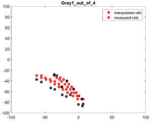
    1. What do these three graphs mean? What do the horizontal and vertical axes represent? I have carefully consulted the AWB plugin guide, but there is no more explanation.
    2. In the WDR mode, the camera has a severe light suppression issue and the image is extremely dark. After debugging the CFA + WDR mode, the image becomes brighter. May I ask whether this is the effect of WDR or GLBCE?
    Thanks!
  • Hi Ying,

    My ISP tuning is basically completed, and the effect is good.

    That is good news to hear!

    1. What do these three graphs mean? What do the horizontal and vertical axes represent? I have carefully consulted the AWB plugin guide, but there is no more explanation.

    These are for the calibration lights/images you provided for AWB tuning.
    Please refer to the plugin guides for the illustrations there.

    2. In the WDR mode, the camera has a severe light suppression issue and the image is extremely dark. After debugging the CFA + WDR mode, the image becomes brighter. May I ask whether this is the effect of WDR or GLBCE?

    I am not sure what you mean by "light suppression issue".
    But, yes, tuning "CFA+WDR" is main for getting bright output images in some sense.

  • BTW, what is the cause of the difference between your latest plot below and the previous plot?

    I don't expect the bad one to happen if you use the correct knee points and black level.