This thread has been locked.

If you have a related question, please click the "Ask a related question" button in the top right corner. The newly created question will be automatically linked to this question.

TMDSCNCD263P: ECAP

Part Number: TMDSCNCD263P
Other Parts Discussed in Thread: UNIFLASH, , TMDSHSECDOCK

Tool/software:

Hey Experts,

ive a question regarding the ECAP module. 
Iam using:
CCS 12.8.1.00005
SDK 10_00_00_35
Uniflash 8.8.1.4983
TMDSCNCD263P PROC159E2

Frist i created a project close to the example code "ecap_capture_pwm".
I configured the ECAP module:

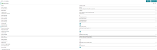
created a PWM at PWM_7A

and mapped ECAP input via inpu xbar to PWM_7A aswell:


results looks fine when i debug the code:


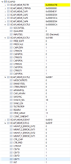
now to simulate a real external signal, i set the xbar input to a different GPIO and connected it at the eval board to the PWM_7A pin by a jumper.

i choosed GPIO 55 which corresponds to HSEC_PIN 58 at eval board. (also testet some other pins but result stays the same).
When i debug the code now, capture registers won't get loaded:

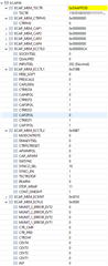
i checked the PWM with an oscilloscope, this looked fine.

Any ideas whats happening here?


Best Regards

Marcel

  • Hello Marcel,

    I'm not sure initially. Reviewing your changes I wouldn't expect that. If you don't make a connection on the board does the results change at all? Also when you got the first results, did you have any board connections made?

    I won't be able to replicate your exact setup tomorrow but I will try and do something similar with AM263P LaunchPad. I can also test with an AM263 controlCard but would need to understand which HSEC dock you have (there's a generic one and AM263x specific one).

    Best Regards,

    Ralph Jacobi

  • Hey Ralph,

    i've got the TMDSHSECDOCK.
    There are some other connections at my evalboard, for example ive connected a AMC1306 eval board, but those connections shouldn't influence my PWM/eCAP connection.
    At my second test ( have another PWM output then the eCAP input ) there is no difference if i have them connected by cable or not. Iam not entirely sure how much input resistance the pins have, but i touched the eCAP input pin with my finger to add some noise. There i would also expect some random edge detection, but the capture registers stay at 0 all the time. 
    Is there anything more i have to do in SW to get the eCAP input connected with the real HW pin then just the input xbar? 
    Perhaps the pin is incorrectly configured as PWM output, can i check this in debug mode in any register? Can i also see in any registers the state of the pin? If its high or low, if i see some toggeling there i have another proof that any HW connection is correct.

    Best Regards,

    Marcel

  • Hi Marcel,

    Sorry for the long delay. I finally found a couple blocks of time the past two afternoons to setup my hardware and load the examples etc. I was able to reproduce the issue quickly but the solution didn't come to mind until my second crack this afternoon.

    The solution is that in order to change the ECAP input pin from one that is already associated with the EPWM, that pin needs to be configured to it's actually active and can tie to the Input XBAR. Adding it to the Input XBAR doesn't enable the pin at a device level, it just enables the event connections. In this case you can just configure it as a standard GPIO input and that's all that is needed:

    As soon as I did that, everything worked as expected.

    As an aside, one quirk that threw me off a bit more today on this is that after you configure the GPIO as an input correctly, if you don't power cycle the board it will remember that across program loads. So when I was verifying the fix initially I was getting a 'pass' on the version without the GPIO input configuration until I power cycled it and then confirmed adding the input was the fix.

    Again sorry it took me so long to get back to you on this.

    Best Regards,

    Ralph Jacobi

  • Hey Ralph,

    many thanks for the answer. This works for me aswell.

    While i was handling with the problem, i tried to find out whats the default pin configuration. I found this here in the datasheet:


    This says the pin is muxed to GPIO55 and not to PWM6A after restart. So the datasheet is incorrect here?

    Best regards,

    Marcel

  • Hi Marcel,

    The datasheet isn't wrong. The mux mode is set correctly to GPIO55. But as you'll see, the Ball State after reset is set to 'off' so while the mux is set for GPIO55, the ball is inactive until configured by the program.

    Best Regards,

    Ralph Jacobi