Tool/software:
#include <stdio.h>
#include <fcntl.h>
#include <unistd.h>
#include <sys/ioctl.h>
#include <linux/spi/spidev.h>
#include <string.h>

#define SPI_DEVICE "/dev/spidev1.0"

void print_hex(const char *label, const unsigned char *data, int len) {
    printf("%s: ", label);
    for (int i = 0; i < len; i++) {
        printf("%02X ", data[i]);
    }
    printf("\n");
}

int main() {
    int fd;
    unsigned char tx[] = {0x9F, 0x00, 0x00, 0x00}; // JEDEC ID command
    unsigned char rx[4] = {0};

    // Open SPI device
    fd = open(SPI_DEVICE, O_RDWR);
    if (fd < 0) {
        perror("Failed to open SPI device");
        return 1;
    }

    // Set SPI mode (SPI_MODE_0)
    int mode = SPI_MODE_0;
    if (ioctl(fd, SPI_IOC_WR_MODE, &mode) < 0) {
        perror("Failed to set SPI mode");
        close(fd);
        return 1;
    }

    // Set max speed (1 MHz)
    int speed = 1000000;
    if (ioctl(fd, SPI_IOC_WR_MAX_SPEED_HZ, &speed) < 0) {
        perror("Failed to set SPI speed");
        close(fd);
        return 1;
    }

    // Set bits per word (8 bits)
    int bits = 8;
    if (ioctl(fd, SPI_IOC_WR_BITS_PER_WORD, &bits) < 0) {
        perror("Failed to set bits per word");
        close(fd);
        return 1;
    }

    // Print SPI settings
    printf("SPI mode: %d\n", mode);
    printf("SPI speed: %d Hz\n", speed);
    printf("SPI bits per word: %d\n", bits);

    // Perform SPI transfer
    struct spi_ioc_transfer tr = {
        .tx_buf = (unsigned long)tx,
        .rx_buf = (unsigned long)rx,
        .len = sizeof(tx),
        .delay_usecs = 0,
        .speed_hz = speed,
        .bits_per_word = bits,
    };

    print_hex("Sending", tx, sizeof(tx));

    if (ioctl(fd, SPI_IOC_MESSAGE(1), &tr) < 0) {
        perror("Failed to perform SPI transfer");
        close(fd);
        return 1;
    }

    print_hex("Received", rx, sizeof(rx));

    // Close SPI device
    close(fd);
    return 0;
}
Hello TI Team,
I am working on a project where I am using the AM3359 SPI1 instance to communicate with a W25Q512JV serial flash memory. Since my project is still in the design phase, I am using a BeagleBone Black development board for proof of concept.
Hardware Connections:
Below are the pin connections between the BeagleBone Black (BBB) and W25Q512JV:
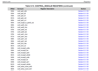
| BeagleBone Black (BBB) | Winbond W25Q512JV | Description |
|---|---|---|
| P9_31 (SPI1_SCLK) | Pin 6 (SCLK) | SPI Clock |
| P9_29 (SPI1_D0) | Pin 2 (DO/MISO) | SPI MISO |
| P9_30 (SPI1_D1) | Pin 5 (DI/MOSI) | SPI MOSI |
| P9_28 (SPI1_CS0) | Pin 1 (CS#) | SPI Chip Select (with 1KΩ pull-up to VCC) |
| P9_3 (3.3V) | Pin 8 (VCC) | Power |
| P9_1 (GND) | Pin 4 (GND) | Ground |
| Pin 3 (WP#) | Connected to VCC (3.3V) | |
| Pin 7 (HOLD#) | Connected to VCC (3.3V) |
Device Tree Configuration:
I have updated my device tree as follows:
&am33xx_pinmux {
spi1_pins: spi1_pins {
pinctrl-single,pins = <
0x190 0x33 /* SPI1_SCLK - P9_31 */
0x194 0x33 /* SPI1_D0 (MISO) - P9_29 */
0x198 0x33 /* SPI1_D1 (MOSI) - P9_30 */
0x19C 0x33 /* SPI1_CS0 - P9_28 */
>;
};
};
&spi1 {
status = "okay";
pinctrl-names = "default";
pinctrl-0 = <&spi1_pins>;
#address-cells = <1>;
#size-cells = <0>;
cs-gpios = <&gpio3 17 0>;
spidev0: spi@0 {
compatible = "spidev";
reg = <0>;
spi-max-frequency = <16000000>; /* 16 MHz */
status = "okay";
};
};
Note: Since AM3359 will need to communicate with multiple Winbond flash chips, I have not yet added the flash chip driver details.
Issue Faced:
After booting into Arago Linux, I checked if the SPI device was created:
ls /dev/spidev*
Output:
/dev/spidev1.0
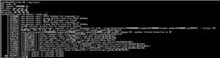
However, when I try to detect the flash chip using flashrom, I get an error:
sudo flashrom -p linux_spi:dev=/dev/spidev1.0,spispeed=8000
Error:
EEPROM device not found
I connected a logic analyzer to monitor the SPI signals and observed that:
- CS pin is toggling LOW during communication.
- No clock (SCLK) signal is generated.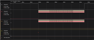
I also tested SPI communication using a sample SPI test program, but no valid data is received from the flash chip.
Could you please review my device tree settings and help identify the root cause of why SPI communication is failing? I would appreciate any guidance on debugging this issue further.
I have attached my sample SPI test program for reference.
Thank you for your support.
BR,
Paul Jins