Tool/software:
Hi, Dear Expert
This is concept question, need your double check
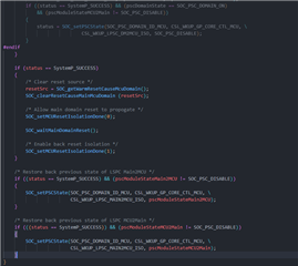
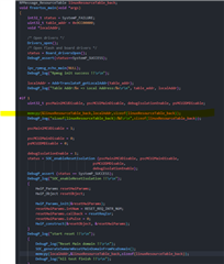
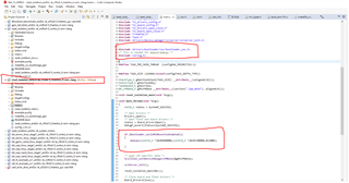
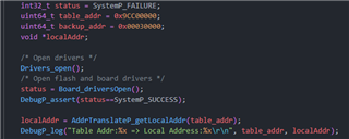
We have an sample code (Reset Isolation - MCU Domain), I think it's FFI (freedom from interference) demo, isn't?
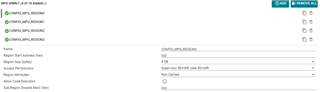
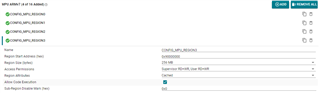
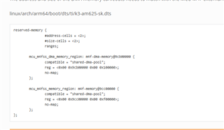
When MCU enter Reset Isolation (FFI?!),
(1) Main and MCU domain peripheral can not access each other, isn't
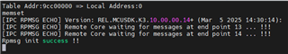
(2) Any IPC service (ex:RPMSG) will be disable, isn't?
Thank You.
Gibbs