


Part Number: DRA821U
Other Parts Discussed in Thread: J7200XSOMXEVM
Tool/software:
Hi Team,
We have designed a custom board based on the J7200XSOMXEVM reference design.
The custom board is connected to FRAM (MB85RS4MT) via QSPI (MCU_OSPI).
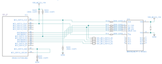
According to the above circuit, We wrote the device tree as follows:
&wkup_pmx0 {
	fram_pins_default: fram-default-pins {
		pinctrl-single,pins = <
			J721E_WKUP_IOPAD(0x0, PIN_OUTPUT, 0) /* (B6) MCU_OSPI0_CLK */
			J721E_WKUP_IOPAD(0x2c, PIN_OUTPUT, 0) /* (D6) MCU_OSPI0_CSn0 */
			J721E_WKUP_IOPAD(0xc, PIN_INPUT, 0) /* (D8) MCU_OSPI0_D0 */
			J721E_WKUP_IOPAD(0x10, PIN_INPUT, 0) /* (C7) MCU_OSPI0_D1 */
			J721E_WKUP_IOPAD(0x14, PIN_INPUT, 0) /* (C5) MCU_OSPI0_D2 */
			J721E_WKUP_IOPAD(0x18, PIN_INPUT, 0) /* (A5) MCU_OSPI0_D3 */
			J721E_WKUP_IOPAD(0x8, PIN_INPUT, 0) /* (B7) MCU_OSPI0_DQS */
			J721E_WKUP_IOPAD(0x4, PIN_INPUT, 0) /* (C8) MCU_OSPI0_LBCLKO */
		>;
	};
};


&ospi0 {
	status = "okay";
	pinctrl-names = "default";
	pinctrl-0 = <&fram_pins_default>;

	mb85rs4mt@0 {
		status = "okay";
		compatible = "jedec,spi-nor", "fujitsu,mb85rs4mt";
		reg = <0x0>;
		spi-tx-bus-width = <4>;
		spi-rx-bus-width = <4>;
		spi-max-frequency = <40000000>;
		cdns,tshsl-ns = <60>;
		cdns,tsd2d-ns = <60>;
		cdns,tchsh-ns = <60>;
		cdns,tslch-ns = <60>;
		cdns,read-delay = <4>;

		partitions {
			compatible = "fixed-partitions";
			#address-cells = <1>;
			#size-cells = <1>;

			partition@0 {
				label = "fram.data";
				reg = <0x00000000 0x000080000>;
			};
		};
	};
};
Also, there was no information on compatibility with mb85rq4ml in "board-support/ti-linux-kernel-6.6.32+git-ti-rt/Documentation/devicetree/bindings/eeprom/at25.yaml". Therefore, we were able to make it compatible by modifying "board-support/ti-linux-kernel-6.6.32+git-ti-rt/drivers/mtd/spi-nor/fujitsu.c" as follows.
// SPDX-License-Identifier: GPL-2.0
/*
 * Copyright (C) 2005, Intec Automation Inc.
 * Copyright (C) 2014, Freescale Semiconductor, Inc.
 */

#include <linux/mtd/spi-nor.h>

#include "core.h"

static const struct flash_info fujitsu_nor_parts[] = {
	/* Fujitsu */
	{ "mb85rs1mt", INFO(0x047f27, 0, 128 * 1024, 1)
		FLAGS(SPI_NOR_NO_ERASE) },
+	{ "mb85rq4ml", INFO(0x047f29, 0, 512 * 1024, 1)
+		FLAGS(SPI_NOR_NO_ERASE)
+		NO_SFDP_FLAGS(SPI_NOR_QUAD_READ) },
};

const struct spi_nor_manufacturer spi_nor_fujitsu = {
	.name = "fujitsu",
	.parts = fujitsu_nor_parts,
	.nparts = ARRAY_SIZE(fujitsu_nor_parts),
};
When We made these settings and started the program, the following message was displayed and the program failed to recognize the FRAM.
~# dmesg | grep spi
[    0.738259] cadence-qspi 47040000.spi: registered master spi0
[    0.738292] spi spi0.0: setup mode 0, 8 bits/w, 40000000 Hz max --> 0
[    0.738857] spi-nor spi0.0: unrecognized JEDEC id bytes: 08 fe 53 0b ff ff
[    0.738884] cadence-qspi 47040000.spi: registered child spi0.0
Since the obtained JEDEC id was different from MB85RS4MT, we checked the following signal lines with an oscilloscope and found no change in the signal.
-MCU_OSPI0_CLK
-MCU_OSPI0_CSn0
-MCU_OSPI0_D0
-MCU_OSPI0_D1
Looking at the source code, it looks like the RDID command is being sent from the OSPI port, but for some reason We can't get the signal waveform.
Do you know what the reason is?
Also, I wanted to check the signals with the SPI driver without using the FRAM driver, but looking at the following forum, it seems that spidev_test cannot be used with OSPI.
Could you please tell me how to investigate the cause?
Regards,
mizutani
