Tool/software:
I want to control the GPIO E18 through echo, but it does not work. May I ask what is the problem


This thread has been locked.
If you have a related question, please click the "Ask a related question" button in the top right corner. The newly created question will be automatically linked to this question.
Tool/software:
I want to control the GPIO E18 through echo, but it does not work. May I ask what is the problem
Hello,
What device tree changes have been made for the GPIO?
What Linux SDK version are you using?
Is this being done on custom hardware or a TI EVM?
Best Regards,
Anshu

// SPDX-License-Identifier: GPL-2.0
/*
* AM625 SK: https://www.ti.com/lit/zip/sprr448
*
* Copyright (C) 2021-2022 Texas Instruments Incorporated - https://www.ti.com/
*/
/dts-v1/;
#include <dt-bindings/leds/common.h>
#include <dt-bindings/gpio/gpio.h>
#include <dt-bindings/input/input.h>
#include <dt-bindings/net/ti-dp83867.h>
#include "k3-am625.dtsi"
#include "k3-am62x-sk-common.dtsi"
/ {
compatible = "ti,am625-sk", "ti,am625";
model = "TL62x-EVM";
aliases {
rtc0 = &ds1340;
rtc1 = &wkup_rtc0;
serial3 = &main_uart1;
serial4 = &main_uart2;
serial5 = &main_uart4;
serial6 = &main_uart5;
serial7 = &main_uart6;
serial8 = &mcu_uart0;
serial9 = &wkup_uart0;
};
transceiver0: can-phy0 {
compatible = "ti,tcan1042";
#phy-cells = <0>;
max-bitrate = <5000000>;
};
transceiver1: can-phy1 {
compatible = "ti,tcan1042";
#phy-cells = <0>;
max-bitrate = <5000000>;
};
opp-table {
/* Add 1.4GHz OPP for am625-sk board. Requires VDD_CORE to be at 0.85V */
opp-1400000000 {
opp-hz = /bits/ 64 <1400000000>;
opp-supported-hw = <0x01 0x0004>;
clock-latency-ns = <6000000>;
};
};
/delete-node/ tlv320_mclk;
tlv320_mclk: clk-0 {
#clock-cells = <0>;
compatible = "fixed-clock";
clock-frequency = <24567000>;
};
/delete-node/ leds;
leds {
compatible = "gpio-leds";
pinctrl-names = "default";
pinctrl-0 = <&main_leds_pins_default &mcu_leds_pins_default>;
som_led0 {
label = "heartbeat";
gpios = <&main_gpio0 1 GPIO_ACTIVE_HIGH>;
linux,default-trigger = "heartbeat";
function = LED_FUNCTION_HEARTBEAT;
default-state = "off";
};
som_led1 {
label = "disk";
gpios = <&main_gpio0 12 GPIO_ACTIVE_HIGH>;
linux,default-trigger = "mmc0";
function = LED_FUNCTION_DISK;
default-state = "off";
};
user_led0 {
label = "user-led0";
gpios = <&main_gpio1 49 GPIO_ACTIVE_HIGH>;
linux,default-trigger = "default-on";
function = LED_FUNCTION_STATUS;
default-state = "off";
};
user_led1 {
label = "user-led1";
gpios = <&main_gpio0 7 GPIO_ACTIVE_HIGH>;
linux,default-trigger = "default-on";
function = LED_FUNCTION_STATUS;
default-state = "off";
};
user_led2 {
label = "user-led2";
gpios = <&mcu_gpio0 12 GPIO_ACTIVE_HIGH>;
linux,default-trigger = "default-on";
function = LED_FUNCTION_STATUS;
default-state = "off";
};
};
gpio-keys {
compatible = "gpio-keys";
autorepeat;
pinctrl-names = "default";
pinctrl-0 = <&main_keys_pins_default &mcu_keys_pins_default>;
user_key@0 {
label = "user-key0";
linux,code = <KEY_PROG1>;
gpios = <&main_gpio0 2 GPIO_ACTIVE_LOW>;
debounce-interval = <0>;
};
user_key@1 {
label = "user-key1";
linux,code = <KEY_PROG2>;
gpios = <&mcu_gpio0 19 GPIO_ACTIVE_LOW>;
debounce-interval = <0>;
};
};
lcd0: display {
compatible = "osddisplays,osd070t1718-19ts", "panel-dpi";
label = "lcd";
port {
lcd_in: endpoint {
remote-endpoint = <&dpi1_out>;
};
};
};
backlight {
compatible = "pwm-backlight";
pinctrl-names = "default";
pinctrl-0 = <&main_ehrpwm1_pins_default>;
pwms = <&epwm1 0 50000 0>;
brightness-levels = <0 10 50 100 150 200 220 240 255>;
default-brightness-level = <8>;
};
codec_audio:sound-tlv320aic3106 {
compatible = "simple-audio-card";
simple-audio-card,name = "AM62x-SKEVM";
simple-audio-card,widgets =
"Line", "Line In Jack",
"Line", "Line Out Jack";
simple-audio-card,routing =
"LINE1L", "Line In Jack",
"LINE1R", "Line In Jack",
"Line Out Jack", "LLOUT",
"Line Out Jack", "RLOUT";
simple-audio-card,format = "dsp_b";
simple-audio-card,bitclock-master = <&sound_master>;
simple-audio-card,frame-master = <&sound_master>;
simple-audio-card,bitclock-inversion;
simple-audio-card,cpu {
sound-dai = <&mcasp0>;
};
sound_master: simple-audio-card,codec {
sound-dai = <&tlv320aic3106>;
clocks = <&tlv320_mclk>;
};
};
clk_ov4689_fixed: ov4689-xclk {
compatible = "fixed-clock";
#clock-cells = <0>;
clock-frequency = <24000000>;
};
};
&mcu_pmx0 {
pinctrl-names = "default";
pinctrl-0 = <&mcu_uart0_control_pins_default &mcu_fan_pins_default &mcu_phy_reset_pins_default>;
mcu_leds_pins_default: mcu_leds_pins_default {
pinctrl-single,pins = <
AM62X_MCU_IOPAD(0x0030, PIN_OUTPUT, 7) /* (A4) WKUP_UART0_RTSn.MCU_GPIO0_12 */
>;
};
mcu_keys_pins_default: mcu_keys_pins_default {
pinctrl-single,pins = <
AM62X_MCU_IOPAD(0x004c, PIN_INPUT, 7) /* (B9) WKUP_I2C0_SCL.MCU_GPIO0_19 */
>;
};
mcu_uart0_pins_default: mcu_uart0_pins_default {
pinctrl-single,pins = <
AM62X_MCU_IOPAD(0x0014, PIN_INPUT, 0) /* (B5) MCU_UART0_RXD */
AM62X_MCU_IOPAD(0x0018, PIN_OUTPUT, 0) /* (A5) MCU_UART0_TXD */
>;
};
mcu_uart0_control_pins_default: mcu-uart0-control-pins-default {
pinctrl-single,pins = <
AM62X_MCU_IOPAD(0x020, PIN_OUTPUT, 7) /* (B6) MCU_UART0_RTSn.MCU_GPIO0_8 */
AM62X_MCU_IOPAD(0x01c, PIN_OUTPUT, 7) /* (A6)MCU_UART0_CTSn.MCU_GPIO0_7 */
>;
};
mcu_fan_pins_default: mcu_fan_pins_default {
pinctrl-single,pins = <
/* set the pull-up, the fan is turned on by default */
AM62X_MCU_IOPAD(0x008, PIN_OUTPUT_PULLUP, 7) /* (A7) MCU_SPI0_CLK.MCU_GPIO0_2 (fan) */
>;
};
mcu_phy_reset_pins_default: mcu_phy_reset_pins_default {
pinctrl-single,pins = <
AM62X_MCU_IOPAD(0x0004, PIN_INPUT_PULLUP, 7) /* (B8) MCU_SPI0_CS1.MCU_GPIO0_1 */
AM62X_MCU_IOPAD(0x000c, PIN_INPUT_PULLUP, 7) /* (D9) MCU_SPI0_D0.MCU_GPIO0_3 */
>;
};
};
&main_pmx0 {
pinctrl-names = "default";
pinctrl-0 = <&main_watchdog_pins_default &main_4g_reset_pins_default &main_isolate_pins_default>;
main_watchdog_pins_default: main_watchdog_pins_default {
pinctrl-single,pins = <
AM62X_IOPAD(0x00ac, PIN_OUTPUT, 7) /* (L21) GPMC0_CSn1.GPIO0_42 */
>;
};
main_4g_reset_pins_default: main_4g_reset_pins_default {
pinctrl-single,pins = <
AM62X_IOPAD(0x0038, PIN_OUTPUT, 7) /* (E24) OSPI0_CSn3.GPIO0_14 */
>;
};
main_isolate_pins_default: main_isolate_pins_default {
pinctrl-single,pins = <
AM62X_IOPAD(0x0090, PIN_INPUT, 7) /* (M24) GPMC0_BE0n_CLE.GPIO0_35 */
AM62X_IOPAD(0x0094, PIN_INPUT, 7) /* (N20) GPMC0_BE1n.GPIO0_36 */
AM62X_IOPAD(0x0098, PIN_INPUT, 7) /* (U23) GPMC0_WAIT0.GPIO0_37 */
AM62X_IOPAD(0x00a4, PIN_INPUT, 7) /* (M22) GPMC0_DIR.GPIO0_40 */
AM62X_IOPAD(0x00a0, PIN_OUTPUT, 7) /* (K25) GPMC0_WPn.GPIO0_39 */
AM62X_IOPAD(0x0110, PIN_OUTPUT, 7) /* (C25) MMC2_DAT1.GPIO0_67 */
AM62X_IOPAD(0x0114, PIN_OUTPUT, 7) /* (B24) MMC2_DAT0.GPIO0_68 */
AM62X_IOPAD(0x01ac, PIN_OUTPUT, 7) /* (E19) MCASP0_AFSR.GPIO1_13 */
>;
};
main_ov4689_reset_pins_default: main_ov4689_reset_pins_default {
pinctrl-single,pins = <
AM62X_IOPAD(0x0034, PIN_OUTPUT_PULLUP, 7) /* (H21) OSPI0_CSn2.GPIO0_13 */
>;
};
main_leds_pins_default: main_leds_pins_default {
pinctrl-single,pins = <
AM62X_IOPAD(0x0004, PIN_OUTPUT, 7) /* (G25) OSPI0_LBCLKO.GPIO0_1 */
AM62X_IOPAD(0x001c, PIN_OUTPUT, 7) /* (J23) OSPI0_D4.GPIO0_7 */
AM62X_IOPAD(0x0030, PIN_OUTPUT, 7) /* (G21) OSPI0_CSn1.GPIO0_12 */
AM62X_IOPAD(0x0244, PIN_OUTPUT, 7) /* (C17) MMC1_SDWP.GPIO1_49 */
>;
};
main_keys_pins_default: main_keys_pins_default {
pinctrl-single,pins = <
AM62X_IOPAD(0x0008, PIN_INPUT, 7) /* (J24) OSPI0_DQS.GPIO0_2 */
>;
};
main_uart1_pins_default: main-uart1-pins-default {
pinctrl-single,pins = <
AM62X_IOPAD(0x01e8, PIN_INPUT, 1) /* (B17) I2C1_SCL.UART1_RXD */
AM62X_IOPAD(0x01ec, PIN_OUTPUT, 1) /* (A17) I2C1_SDA.UART1_TXD */
>;
};
main_uart2_pins_default: main-uart2-pins-default {
pinctrl-single,pins = <
AM62X_IOPAD(0x01d0, PIN_INPUT, 3) /* (A15) UART0_CTSn.UART2_RXD */
AM62X_IOPAD(0x01d4, PIN_OUTPUT, 3) /* (B15) UART0_RTSn.UART2_TXD */
>;
};
main_uart4_pins_default: main-uart4-pins-default {
pinctrl-single,pins = <
AM62X_IOPAD(0x0124, PIN_INPUT, 3) /* (A23) MMC2_SDCD.UART4_RXD */
AM62X_IOPAD(0x0128, PIN_OUTPUT, 3) /* (B23) MMC2_SDWP.UART4_TXD */
>;
};
main_uart5_pins_default: main-uart5-pins-default {
pinctrl-single,pins = <
AM62X_IOPAD(0x0108, PIN_INPUT, 3) /* (D24) MMC2_DAT3.UART5_RXD */
AM62X_IOPAD(0x010c, PIN_OUTPUT, 3) /* (E23) MMC2_DAT2.UART5_TXD */
>;
};
main_uart6_pins_default: main-uart6-pins-default {
pinctrl-single,pins = <
AM62X_IOPAD(0x0118, PIN_INPUT, 3) /* (D25) MMC2_CLK.UART6_RXD */
AM62X_IOPAD(0x0120, PIN_OUTPUT, 3) /* (C24) MMC2_CMD.UART6_TXD */
>;
};
main_ehrpwm1_pins_default: main_ehrpwm1_pins_default {
pinctrl-single,pins = <
AM62X_IOPAD(0x019c, PIN_OUTPUT, 6) /* (B18) MCASP0_AXR1.EHRPWM1_A */
>;
};
main_spi0_clk_data_pins_default: main_spi0_clk_data_pins_default {
pinctrl-single,pins = <
AM62X_IOPAD(0x01bc, PIN_OUTPUT, 0) /* (A14) SPI0_CLK */
AM62X_IOPAD(0x01c0, PIN_INPUT, 0) /* (B13) SPI0_D0 */
AM62X_IOPAD(0x01c4, PIN_INPUT, 0) /* (B14) SPI0_D1 */
>;
};
main_spi0_cs0_pins_default: main_spi0_cs0_pins_default {
pinctrl-single,pins = <
AM62X_IOPAD(0x01b4, PIN_OUTPUT_PULLUP, 0) /* (A13) SPI0_CS0 */
>;
};
main_ads7846_pins_default: main_ads7846_pins_default {
pinctrl-single,pins = <
AM62X_IOPAD(0x01f0, PIN_INPUT_PULLUP, 7) /* (A18) EXT_REFCLK1.GPIO1_30 */
>;
};
main_usb0_pins_default: main_usb0_pins_default {
pinctrl-single,pins = <
AM62X_IOPAD(0x0254, PIN_OUTPUT, 0) /* (C20) USB0_DRVVBUS */
>;
};
main_mcan0_pins_default: main_mcan0_pins_default {
pinctrl-single,pins = <
AM62X_IOPAD(0x01dc, PIN_INPUT, 0) /* (E15) MCAN0_RX */
AM62X_IOPAD(0x01d8, PIN_OUTPUT, 0) /* (C15) MCAN0_TX */
>;
};
main_mcasp0_pins_default: main-mcasp0-pins-default {
pinctrl-single,pins = <
AM62X_IOPAD(0x01B0, PIN_OUTPUT, 0) /* (A20) MCASP0_ACLKR.MCASP0_ACLKR */
AM62X_IOPAD(0x01A4, PIN_INPUT, 0) /* (B20) MCASP0_ACLKX.MCASP0_ACLKX */
AM62X_IOPAD(0x01A8, PIN_INPUT, 0) /* (D20) MCASP0_AFSX.MCASP0_AFSX */
AM62X_IOPAD(0x0198, PIN_OUTPUT, 0) /* (A19) MCASP0_AXR2.MCASP0_AXR2 */
AM62X_IOPAD(0x0194, PIN_INPUT, 0) /* (B19) MCASP0_AXR3.MCASP0_AXR3 */
>;
};
main_pmic_intr_pins_default: main_pmic_intr_pins_default {
pinctrl-single,pins = <
AM62X_IOPAD(0x01f4, PIN_INPUT_PULLUP, 7) /* (D16) EXTINTn.GPIO1_31 */
>;
};
};
&main_i2c0 {
ds1340: rtc@68 {
compatible = "dallas,ds1340";
reg = <0x68>;
trickle-resistor-ohms = <250>;
};
tps65219: pmic@30 {
compatible = "ti,tps65219";
reg = <0x30>;
buck1-supply = <&vcc_3v3_sys>;
buck2-supply = <&vcc_3v3_sys>;
buck3-supply = <&vcc_3v3_sys>;
ldo1-supply = <&vcc_3v3_sys>;
ldo2-supply = <&buck2_reg>;
ldo3-supply = <&vcc_3v3_sys>;
ldo4-supply = <&vcc_3v3_sys>;
pinctrl-0 = <&main_pmic_intr_pins_default>;
interrupt-parent = <&main_gpio1>;
interrupts = <31 0>; /* gpio1_31 */
interrupt-controller;
#interrupt-cells = <1>;
/* turn off the temperature warning function */
sensor-warm-mask;
regulators {
buck1_reg: buck1 {
regulator-name = "VDD_0V85_CORE";
regulator-min-microvolt = <850000>;
regulator-max-microvolt = <850000>;
regulator-boot-on;
regulator-always-on;
};
buck2_reg: buck2 {
regulator-name = "VDD_1V8_MAIN";
regulator-min-microvolt = <1800000>;
regulator-max-microvolt = <1800000>;
regulator-boot-on;
regulator-always-on;
};
buck3_reg: buck3 {
regulator-name = "VDD_1V2_MAIN";
regulator-min-microvolt = <1200000>;
regulator-max-microvolt = <1200000>;
regulator-boot-on;
regulator-always-on;
};
ldo1_reg: ldo1 {
regulator-name = "VDD_3V3_LDO1";
regulator-min-microvolt = <3300000>;
regulator-max-microvolt = <3300000>;
};
ldo2_reg: ldo2 {
regulator-name = "VDD_1V8_LDO2";
regulator-min-microvolt = <1800000>;
regulator-max-microvolt = <1800000>;
regulator-boot-on;
regulator-always-on;
};
ldo3_reg: ldo3 {
regulator-name = "VDD_1V8_LDO3";
regulator-min-microvolt = <1800000>;
regulator-max-microvolt = <1800000>;
regulator-boot-on;
regulator-always-on;
};
ldo4_reg: ldo4 {
regulator-name = "VDD_2V5_LDO4";
regulator-min-microvolt = <2500000>;
regulator-max-microvolt = <2500000>;
regulator-boot-on;
regulator-always-on;
};
};
};
};
&main_i2c1 {
};
&ospi0 {
spi_nor_flash: flash@0 {
compatible = "jedec,spi-nor";
reg = <0x0>;
spi-tx-bus-width = <4>;
spi-rx-bus-width = <4>;
spi-max-frequency = <25000000>;
cdns,tshsl-ns = <60>;
cdns,tsd2d-ns = <60>;
cdns,tchsh-ns = <60>;
cdns,tslch-ns = <60>;
cdns,read-delay = <4>;
cdns,phy-mode;
partitions {
compatible = "fixed-partitions";
#address-cells = <1>;
#size-cells = <1>;
partition@0 {
label = "ospi.tiboot3";
reg = <0x0 0x80000>;
};
partition@80000 {
label = "ospi.tispl";
reg = <0x80000 0x100000>;
};
partition@180000 {
label = "ospi.u-boot";
reg = <0x180000 0x200000>;
};
partition@380000 {
label = "ospi.env";
reg = <0x380000 0x40000>;
};
partition@3c0000 {
label = "ospi.env.backup";
reg = <0x3c0000 0x40000>;
};
partition@400000 {
label = "ospi.rootfs";
reg = <0x400000 0x0>;
};
};
};
};
&main_uart1 {
status = "okay";
pinctrl-names = "default";
pinctrl-0 = <&main_uart1_pins_default>;
};
&main_uart2 {
status = "okay";
pinctrl-names = "default";
pinctrl-0 = <&main_uart2_pins_default>;
};
&main_uart4 {
status = "okay";
pinctrl-names = "default";
pinctrl-0 = <&main_uart4_pins_default>;
};
&main_uart5 {
status = "okay";
pinctrl-names = "default";
pinctrl-0 = <&main_uart5_pins_default>;
};
&main_uart6 {
status = "okay";
pinctrl-names = "default";
pinctrl-0 = <&main_uart6_pins_default>;
};
&lcd0 {
panel-timing {
clock-frequency = <33000000>;
hactive = <800>;
vactive = <480>;
hfront-porch = <210>;
hback-porch = <16>;
hsync-len = <30>;
vback-porch = <10>;
vfront-porch = <22>;
vsync-len = <13>;
hsync-active = <0>;
vsync-active = <0>;
de-active = <1>;
pixelclk-active = <1>;
};
};
&dss_ports {
#address-cells = <1>;
#size-cells = <0>;
/* VP2: DPI Output */
port@1 {
reg = <1>;
dpi1_out: endpoint {
remote-endpoint = <&lcd_in>;
};
};
};
&epwm1 {
status = "okay";
};
&main_spi0 {
status = "okay";
pinctrl-names = "default";
pinctrl-0 = <&main_spi0_clk_data_pins_default &main_spi0_cs0_pins_default>;
ti,pindir-d0-in-d1-out;
ads7846@0 {
compatible = "ti,ads7846";
pinctrl-names = "default";
pinctrl-0 = <&main_ads7846_pins_default>;
reg = <0>; /* CS0 */
spi-max-frequency = <1500000>;
interrupt-parent = <&main_gpio1>;
interrupts = <30 0>; /* gpio1_30 */
pendown-gpio = <&main_gpio1 30 0>;
ti,x-min = /bits/ 16 <0x0>;
ti,x-max = /bits/ 16 <0x0fff>;
ti,y-min = /bits/ 16 <0x0>;
ti,y-max = /bits/ 16 <0x0fff>;
ti,x-plate-ohms = /bits/ 16 <625>;
ti,pressure-max = /bits/ 16 <4095>;
ti,debounce-max = /bits/ 16 <10>;
ti,debounce-tol = /bits/ 16 <30>;
ti,debounce-rep = /bits/ 16 <1>;
ti,settle-delay-usec = /bits/ 16 <150>;
ti,keep-vref-on = <1>;
linux,wakeup;
};
};
&usb0 {
pinctrl-names = "default";
pinctrl-0 = <&main_usb0_pins_default>;
#address-cells = <1>;
#size-cells = <0>;
usb-role-switch;
role-switch-default-mode = "host";
};
&main_mcan0 {
status = "okay";
pinctrl-names = "default";
pinctrl-0 = <&main_mcan0_pins_default>;
};
&main_i2c2 {
status = "okay";
pinctrl-names = "default";
pinctrl-0 = <&main_i2c2_pins_default>;
clock-frequency = <400000>;
tlv320aic3106: audio-codec@18 {
#sound-dai-cells = <0>;
compatible = "ti,tlv320aic3106";
reg = <0x18>;
/* Regulators */
AVDD-supply = <&vcc_3v3_sys>;
IOVDD-supply = <&vcc_3v3_sys>;
DRVDD-supply = <&vcc_3v3_sys>;
DVDD-supply = <&vcc_1v8>;
};
ov4689_mipi: ov4689_mipi@36 {
status = "okay";
compatible = "ovti,ov4689";
pinctrl-names = "default";
pinctrl-0 = <&main_ov4689_reset_pins_default>;
reg = <0x36>;
clocks = <&clk_ov4689_fixed>;
clock-names = "xvclk";
reset-gpios = <&main_gpio0 13 GPIO_ACTIVE_LOW>;
orientation = <2>;
rotation = <0>;
assigned-clocks = <&clk_ov4689_fixed>;
assigned-clock-rates = <24000000>;
csi_id = <0>;
mclk = <24000000>;
mclk_source = <0>;
port {
csi2_cam0: endpoint {
remote-endpoint = <&csi2rx0_in_sensor>;
clock-lanes = <0>;
data-lanes = <1 2 3 4>;
link-frequencies = /bits/ 64 <500000000>;
};
};
};
};
&mcasp0 {
status = "okay";
#sound-dai-cells = <0>;
pinctrl-names = "default";
pinctrl-0 = <&main_mcasp0_pins_default>;
op-mode = <0>; /* MCASP_IIS_MODE */
tdm-slots = <2>;
serial-dir = < /* 0: INACTIVE, 1: TX, 2: RX */
0 0 1 2
0 0 0 0
0 0 0 0
0 0 0 0
>;
tx-num-evt = <32>;
rx-num-evt = <32>;
};
&mcu_pmx0 {
wkup_uart0_pins_default: wkup-uart0-pins-default {
pinctrl-single,pins = <
AM62X_MCU_IOPAD(0x0024, PIN_INPUT, 0) /* (B4) WKUP_UART0_RXD */
AM62X_MCU_IOPAD(0x0028, PIN_OUTPUT, 0) /* (C5) WKUP_UART0_TXD */
>;
};
};
&wkup_uart0 {
status = "okay";
pinctrl-names = "default";
pinctrl-0 = <&wkup_uart0_pins_default>;
};
&mcu_uart0 {
status = "okay";
pinctrl-names = "default";
pinctrl-0 = <&mcu_uart0_pins_default>;
};
&csi0_port0 {
status = "okay";
csi2rx0_in_sensor: endpoint {
remote-endpoint = <&csi2_cam0>;
bus-type = <4>; /* CSI2 DPHY. */
clock-lanes = <0>;
data-lanes = <1 2 3 4>;
};
};
&cpsw3g_mdio {
reset-gpios = <&mcu_gpio0 1 GPIO_ACTIVE_LOW \
&mcu_gpio0 3 GPIO_ACTIVE_LOW>;
reset-delay-us = <100>; /* set reset hold time to 100us */
};
&pruss {
status = "disabled";
};
&main_rti1 {
status = "disabled";
};
&main_rti2 {
status = "disabled";
};
&main_rti3 {
status = "disabled";
};
&main_rti15 {
status = "disabled";
};
&mcu_pmx0 {
mcu_mcan0_pins_default: mcu_mcan0_pins_default {
pinctrl-single,pins = <
AM62X_MCU_IOPAD(0x0038, PIN_INPUT, 0) /* (B3) MCU_MCAN0_RX */
AM62X_MCU_IOPAD(0x0034, PIN_OUTPUT, 0) /* (D6) MCU_MCAN0_TX */
>;
};
mcu_mcan1_pins_default: mcu_mcan1_pins_default {
pinctrl-single,pins = <
AM62X_MCU_IOPAD(0x0040, PIN_INPUT, 0) /* (D4) MCU_MCAN1_RX */
AM62X_MCU_IOPAD(0x003c, PIN_OUTPUT, 0) /* (E5) MCU_MCAN1_TX */
>;
};
};
&mcu_mcan0 {
status = "okay";
pinctrl-names = "default";
pinctrl-0 = <&mcu_mcan0_pins_default>;
phys = <&transceiver0>;
};
&mcu_mcan1 {
status = "okay";
pinctrl-names = "default";
pinctrl-0 = <&mcu_mcan1_pins_default>;
phys = <&transceiver1>;
};
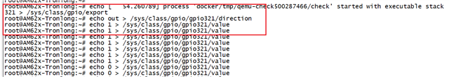
The SDK version I use is ti-processor-sdk-linux-rt-am62xx-evm-08.06.00.42 and I am making my own hardware operation, and the gpio port is connected to a relay. Now I want to test whether the function is normal, but I find that the gpio port cannot be controlled.

Hello,
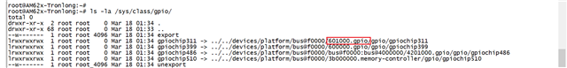
Can you explain how gpio321 was calculated? What is the base number of GPIO0? This can be checked by running 'ls -la /sys/class/gpio' so the GPIO addresses are readable.
Have you try changing the pin control name to 'main_4g_reset_pins_default: main-4g-reset-pins-default' ? I want to make sure the pinctrl-0 is finding the correct node.
Best Regards,
Anshu
There seems to be no change pin in the device tree, should I add it to the device tree? What should the complete process look like
Hello,
The GPIO doesn't need to be added to k3-am62-main.dtsi file. Its used to initialize the module.
Just to make sure, you are using a ALW package, correct?
For a very simple test, try adding this to the device tree for the GPIO:
&main_pmx0 {
    main_gpio0_14_pins_default: main-gpio0-14-pins-default {
		    pinctrl-single,pins = <
			    AM62X_IOPAD(0x0038, PIN_OUTPUT, 7) /* (E24) OSPI0_CSn3.GPIO0_14 */
		    >;
    };
};

&main_gpio0 {
    status = "okay";
    pinctrl-names = "default";
    pinctrl-0 = <&main_gpio0_14_pins_default>;
};
Best Regards,
Anshu
From the device tree you provided, GPIO1_14 is not enabled anywhere. GPIO0_14 is enabled.
This is what I see in your device tree:
main_4g_reset_pins_default: main_4g_reset_pins_default {
		pinctrl-single,pins = <
			AM62X_IOPAD(0x0038, PIN_OUTPUT, 7) /* (E24) OSPI0_CSn3.GPIO0_14 */
		>;
};Anshu
I used this method and found that I could not control it successfully, I used the E18/<MCASP0_AXR0/PR0_ECAP0_IN_APWM_OUT/AUDIO_EXT_REFCLK0/PR0_UART0_TXD/EHRPWM1_B/GPIO1_10/EQEP0_I>/3V3 pin
// SPDX-License-Identifier: GPL-2.0
/*
* AM625 SK: https://www.ti.com/lit/zip/sprr448
*
* Copyright (C) 2021-2022 Texas Instruments Incorporated - https://www.ti.com/
*/
/dts-v1/;
#include <dt-bindings/leds/common.h>
#include <dt-bindings/gpio/gpio.h>
#include <dt-bindings/input/input.h>
#include <dt-bindings/net/ti-dp83867.h>
#include "k3-am625.dtsi"
#include "k3-am62x-sk-common.dtsi"
/ {
compatible = "ti,am625-sk", "ti,am625";
model = "TL62x-EVM";
aliases {
rtc0 = &ds1340;
rtc1 = &wkup_rtc0;
serial3 = &main_uart1;
serial4 = &main_uart2;
serial5 = &main_uart4;
serial6 = &main_uart5;
serial7 = &main_uart6;
serial8 = &mcu_uart0;
serial9 = &wkup_uart0;
};
transceiver0: can-phy0 {
compatible = "ti,tcan1042";
#phy-cells = <0>;
max-bitrate = <5000000>;
};
transceiver1: can-phy1 {
compatible = "ti,tcan1042";
#phy-cells = <0>;
max-bitrate = <5000000>;
};
opp-table {
/* Add 1.4GHz OPP for am625-sk board. Requires VDD_CORE to be at 0.85V */
opp-1400000000 {
opp-hz = /bits/ 64 <1400000000>;
opp-supported-hw = <0x01 0x0004>;
clock-latency-ns = <6000000>;
};
};
/delete-node/ tlv320_mclk;
tlv320_mclk: clk-0 {
#clock-cells = <0>;
compatible = "fixed-clock";
clock-frequency = <24567000>;
};
/delete-node/ leds;
leds {
compatible = "gpio-leds";
pinctrl-names = "default";
pinctrl-0 = <&main_leds_pins_default &mcu_leds_pins_default>;
som_led0 {
label = "heartbeat";
gpios = <&main_gpio0 1 GPIO_ACTIVE_HIGH>;
linux,default-trigger = "heartbeat";
function = LED_FUNCTION_HEARTBEAT;
default-state = "off";
};
som_led1 {
label = "disk";
gpios = <&main_gpio0 12 GPIO_ACTIVE_HIGH>;
linux,default-trigger = "mmc0";
function = LED_FUNCTION_DISK;
default-state = "off";
};
user_led0 {
label = "user-led0";
gpios = <&main_gpio1 49 GPIO_ACTIVE_HIGH>;
linux,default-trigger = "default-on";
function = LED_FUNCTION_STATUS;
default-state = "off";
};
user_led1 {
label = "user-led1";
gpios = <&main_gpio0 7 GPIO_ACTIVE_HIGH>;
linux,default-trigger = "default-on";
function = LED_FUNCTION_STATUS;
default-state = "off";
};
user_led2 {
label = "user-led2";
gpios = <&mcu_gpio0 12 GPIO_ACTIVE_HIGH>;
linux,default-trigger = "default-on";
function = LED_FUNCTION_STATUS;
default-state = "off";
};
};
gpio-keys {
compatible = "gpio-keys";
autorepeat;
pinctrl-names = "default";
pinctrl-0 = <&main_keys_pins_default &mcu_keys_pins_default>;
user_key@0 {
label = "user-key0";
linux,code = <KEY_PROG1>;
gpios = <&main_gpio0 2 GPIO_ACTIVE_LOW>;
debounce-interval = <0>;
};
user_key@1 {
label = "user-key1";
linux,code = <KEY_PROG2>;
gpios = <&mcu_gpio0 19 GPIO_ACTIVE_LOW>;
debounce-interval = <0>;
};
};
lcd0: display {
compatible = "osddisplays,osd070t1718-19ts", "panel-dpi";
label = "lcd";
port {
lcd_in: endpoint {
remote-endpoint = <&dpi1_out>;
};
};
};
/*
backlight {
compatible = "pwm-backlight";
pinctrl-names = "default";
pinctrl-0 = <&main_ehrpwm1_pins_default>;
pwms = <&epwm1 0 50000 0>;
brightness-levels = <0 10 50 100 150 200 220 240 255>;
default-brightness-level = <8>;
};
*/
codec_audio:sound-tlv320aic3106 {
compatible = "simple-audio-card";
simple-audio-card,name = "AM62x-SKEVM";
simple-audio-card,widgets =
"Line", "Line In Jack",
"Line", "Line Out Jack";
simple-audio-card,routing =
"LINE1L", "Line In Jack",
"LINE1R", "Line In Jack",
"Line Out Jack", "LLOUT",
"Line Out Jack", "RLOUT";
simple-audio-card,format = "dsp_b";
simple-audio-card,bitclock-master = <&sound_master>;
simple-audio-card,frame-master = <&sound_master>;
simple-audio-card,bitclock-inversion;
simple-audio-card,cpu {
sound-dai = <&mcasp0>;
};
sound_master: simple-audio-card,codec {
sound-dai = <&tlv320aic3106>;
clocks = <&tlv320_mclk>;
};
};
clk_ov4689_fixed: ov4689-xclk {
compatible = "fixed-clock";
#clock-cells = <0>;
clock-frequency = <24000000>;
};
};
&mcu_pmx0 {
pinctrl-names = "default";
pinctrl-0 = <&mcu_uart0_control_pins_default &mcu_fan_pins_default &mcu_phy_reset_pins_default>;
mcu_leds_pins_default: mcu_leds_pins_default {
pinctrl-single,pins = <
AM62X_MCU_IOPAD(0x0030, PIN_OUTPUT, 7) /* (A4) WKUP_UART0_RTSn.MCU_GPIO0_12 */
>;
};
mcu_keys_pins_default: mcu_keys_pins_default {
pinctrl-single,pins = <
AM62X_MCU_IOPAD(0x004c, PIN_INPUT, 7) /* (B9) WKUP_I2C0_SCL.MCU_GPIO0_19 */
>;
};
mcu_uart0_pins_default: mcu_uart0_pins_default {
pinctrl-single,pins = <
AM62X_MCU_IOPAD(0x0014, PIN_INPUT, 0) /* (B5) MCU_UART0_RXD */
AM62X_MCU_IOPAD(0x0018, PIN_OUTPUT, 0) /* (A5) MCU_UART0_TXD */
>;
};
mcu_uart0_control_pins_default: mcu-uart0-control-pins-default {
pinctrl-single,pins = <
AM62X_MCU_IOPAD(0x020, PIN_OUTPUT, 7) /* (B6) MCU_UART0_RTSn.MCU_GPIO0_8 */
AM62X_MCU_IOPAD(0x01c, PIN_OUTPUT, 7) /* (A6)MCU_UART0_CTSn.MCU_GPIO0_7 */
>;
};
mcu_fan_pins_default: mcu_fan_pins_default {
pinctrl-single,pins = <
/* set the pull-up, the fan is turned on by default */
AM62X_MCU_IOPAD(0x008, PIN_OUTPUT_PULLUP, 7) /* (A7) MCU_SPI0_CLK.MCU_GPIO0_2 (fan) */
>;
};
mcu_phy_reset_pins_default: mcu_phy_reset_pins_default {
pinctrl-single,pins = <
AM62X_MCU_IOPAD(0x0004, PIN_INPUT_PULLUP, 7) /* (B8) MCU_SPI0_CS1.MCU_GPIO0_1 */
AM62X_MCU_IOPAD(0x000c, PIN_INPUT_PULLUP, 7) /* (D9) MCU_SPI0_D0.MCU_GPIO0_3 */
>;
};
};
&main_pmx0 {
pinctrl-names = "default";
pinctrl-0 = <&main_watchdog_pins_default &main_4g_reset_pins_default &main_isolate_pins_default>;
main_watchdog_pins_default: main_watchdog_pins_default {
pinctrl-single,pins = <
AM62X_IOPAD(0x00ac, PIN_OUTPUT, 7) /* (L21) GPMC0_CSn1.GPIO0_42 */
>;
};
main_4g_reset_pins_default: main_4g_reset_pins_default {
pinctrl-single,pins = <
AM62X_IOPAD(0x0038, PIN_OUTPUT, 7) /* (E24) OSPI0_CSn3.GPIO0_14 */
>;
};
main_isolate_pins_default: main_isolate_pins_default {
pinctrl-single,pins = <
AM62X_IOPAD(0x0090, PIN_INPUT, 7) /* (M24) GPMC0_BE0n_CLE.GPIO0_35 */
AM62X_IOPAD(0x0094, PIN_INPUT, 7) /* (N20) GPMC0_BE1n.GPIO0_36 */
AM62X_IOPAD(0x0098, PIN_INPUT, 7) /* (U23) GPMC0_WAIT0.GPIO0_37 */
AM62X_IOPAD(0x00a4, PIN_INPUT, 7) /* (M22) GPMC0_DIR.GPIO0_40 */
AM62X_IOPAD(0x00a0, PIN_OUTPUT, 7) /* (K25) GPMC0_WPn.GPIO0_39 */
AM62X_IOPAD(0x0110, PIN_OUTPUT, 7) /* (C25) MMC2_DAT1.GPIO0_67 */
AM62X_IOPAD(0x0114, PIN_OUTPUT, 7) /* (B24) MMC2_DAT0.GPIO0_68 */
AM62X_IOPAD(0x01ac, PIN_OUTPUT, 7) /* (E19) MCASP0_AFSR.GPIO1_13 */
>;
};
main_ov4689_reset_pins_default: main_ov4689_reset_pins_default {
pinctrl-single,pins = <
AM62X_IOPAD(0x0034, PIN_OUTPUT_PULLUP, 7) /* (H21) OSPI0_CSn2.GPIO0_13 */
>;
};
main_leds_pins_default: main_leds_pins_default {
pinctrl-single,pins = <
AM62X_IOPAD(0x0004, PIN_OUTPUT, 7) /* (G25) OSPI0_LBCLKO.GPIO0_1 */
AM62X_IOPAD(0x001c, PIN_OUTPUT, 7) /* (J23) OSPI0_D4.GPIO0_7 */
AM62X_IOPAD(0x0030, PIN_OUTPUT, 7) /* (G21) OSPI0_CSn1.GPIO0_12 */
AM62X_IOPAD(0x0244, PIN_OUTPUT, 7) /* (C17) MMC1_SDWP.GPIO1_49 */
>;
};
main_keys_pins_default: main_keys_pins_default {
pinctrl-single,pins = <
AM62X_IOPAD(0x0008, PIN_INPUT, 7) /* (J24) OSPI0_DQS.GPIO0_2 */
>;
};
main_uart1_pins_default: main-uart1-pins-default {
pinctrl-single,pins = <
AM62X_IOPAD(0x01e8, PIN_INPUT, 1) /* (B17) I2C1_SCL.UART1_RXD */
AM62X_IOPAD(0x01ec, PIN_OUTPUT, 1) /* (A17) I2C1_SDA.UART1_TXD */
>;
};
main_uart2_pins_default: main-uart2-pins-default {
pinctrl-single,pins = <
AM62X_IOPAD(0x01d0, PIN_INPUT, 3) /* (A15) UART0_CTSn.UART2_RXD */
AM62X_IOPAD(0x01d4, PIN_OUTPUT, 3) /* (B15) UART0_RTSn.UART2_TXD */
>;
};
main_uart4_pins_default: main-uart4-pins-default {
pinctrl-single,pins = <
AM62X_IOPAD(0x0124, PIN_INPUT, 3) /* (A23) MMC2_SDCD.UART4_RXD */
AM62X_IOPAD(0x0128, PIN_OUTPUT, 3) /* (B23) MMC2_SDWP.UART4_TXD */
>;
};
main_uart5_pins_default: main-uart5-pins-default {
pinctrl-single,pins = <
AM62X_IOPAD(0x0108, PIN_INPUT, 3) /* (D24) MMC2_DAT3.UART5_RXD */
AM62X_IOPAD(0x010c, PIN_OUTPUT, 3) /* (E23) MMC2_DAT2.UART5_TXD */
>;
};
main_uart6_pins_default: main-uart6-pins-default {
pinctrl-single,pins = <
AM62X_IOPAD(0x0118, PIN_INPUT, 3) /* (D25) MMC2_CLK.UART6_RXD */
AM62X_IOPAD(0x0120, PIN_OUTPUT, 3) /* (C24) MMC2_CMD.UART6_TXD */
>;
};
main_ehrpwm1_pins_default: main_ehrpwm1_pins_default {
pinctrl-single,pins = <
AM62X_IOPAD(0x01a0, PIN_OUTPUT, 6)
>;
};
/*
main_gpio1_10_pins_default: main-gpio1-10-pins-default {
pinctrl-single,pins = <
AM62X_IOPAD(0x01a0, PIN_OUTPUT, 6)
>;
};
*/
main_spi0_clk_data_pins_default: main_spi0_clk_data_pins_default {
pinctrl-single,pins = <
AM62X_IOPAD(0x01bc, PIN_OUTPUT, 0) /* (A14) SPI0_CLK */
AM62X_IOPAD(0x01c0, PIN_INPUT, 0) /* (B13) SPI0_D0 */
AM62X_IOPAD(0x01c4, PIN_INPUT, 0) /* (B14) SPI0_D1 */
>;
};
main_spi0_cs0_pins_default: main_spi0_cs0_pins_default {
pinctrl-single,pins = <
AM62X_IOPAD(0x01b4, PIN_OUTPUT_PULLUP, 0) /* (A13) SPI0_CS0 */
>;
};
main_ads7846_pins_default: main_ads7846_pins_default {
pinctrl-single,pins = <
AM62X_IOPAD(0x01f0, PIN_INPUT_PULLUP, 7) /* (A18) EXT_REFCLK1.GPIO1_30 */
>;
};
main_usb0_pins_default: main_usb0_pins_default {
pinctrl-single,pins = <
AM62X_IOPAD(0x0254, PIN_OUTPUT, 0) /* (C20) USB0_DRVVBUS */
>;
};
main_mcan0_pins_default: main_mcan0_pins_default {
pinctrl-single,pins = <
AM62X_IOPAD(0x01dc, PIN_INPUT, 0) /* (E15) MCAN0_RX */
AM62X_IOPAD(0x01d8, PIN_OUTPUT, 0) /* (C15) MCAN0_TX */
>;
};
main_mcasp0_pins_default: main-mcasp0-pins-default {
pinctrl-single,pins = <
AM62X_IOPAD(0x01B0, PIN_OUTPUT, 0) /* (A20) MCASP0_ACLKR.MCASP0_ACLKR */
AM62X_IOPAD(0x01A4, PIN_INPUT, 0) /* (B20) MCASP0_ACLKX.MCASP0_ACLKX */
AM62X_IOPAD(0x01A8, PIN_INPUT, 0) /* (D20) MCASP0_AFSX.MCASP0_AFSX */
AM62X_IOPAD(0x0198, PIN_OUTPUT, 0) /* (A19) MCASP0_AXR2.MCASP0_AXR2 */
AM62X_IOPAD(0x0194, PIN_INPUT, 0) /* (B19) MCASP0_AXR3.MCASP0_AXR3 */
>;
};
main_pmic_intr_pins_default: main_pmic_intr_pins_default {
pinctrl-single,pins = <
AM62X_IOPAD(0x01f4, PIN_INPUT_PULLUP, 7) /* (D16) EXTINTn.GPIO1_31 */
>;
};
};
/*
&main_gpio1 {
status = "okay";
pinctrl-names = "default";
pinctrl-0 = <&main_gpio1_10_pins_default>;
};
*/
&main_i2c0 {
ds1340: rtc@68 {
compatible = "dallas,ds1340";
reg = <0x68>;
trickle-resistor-ohms = <250>;
};
tps65219: pmic@30 {
compatible = "ti,tps65219";
reg = <0x30>;
buck1-supply = <&vcc_3v3_sys>;
buck2-supply = <&vcc_3v3_sys>;
buck3-supply = <&vcc_3v3_sys>;
ldo1-supply = <&vcc_3v3_sys>;
ldo2-supply = <&buck2_reg>;
ldo3-supply = <&vcc_3v3_sys>;
ldo4-supply = <&vcc_3v3_sys>;
pinctrl-0 = <&main_pmic_intr_pins_default>;
interrupt-parent = <&main_gpio1>;
interrupts = <31 0>; /* gpio1_31 */
interrupt-controller;
#interrupt-cells = <1>;
/* turn off the temperature warning function */
sensor-warm-mask;
regulators {
buck1_reg: buck1 {
regulator-name = "VDD_0V85_CORE";
regulator-min-microvolt = <850000>;
regulator-max-microvolt = <850000>;
regulator-boot-on;
regulator-always-on;
};
buck2_reg: buck2 {
regulator-name = "VDD_1V8_MAIN";
regulator-min-microvolt = <1800000>;
regulator-max-microvolt = <1800000>;
regulator-boot-on;
regulator-always-on;
};
buck3_reg: buck3 {
regulator-name = "VDD_1V2_MAIN";
regulator-min-microvolt = <1200000>;
regulator-max-microvolt = <1200000>;
regulator-boot-on;
regulator-always-on;
};
ldo1_reg: ldo1 {
regulator-name = "VDD_3V3_LDO1";
regulator-min-microvolt = <3300000>;
regulator-max-microvolt = <3300000>;
};
ldo2_reg: ldo2 {
regulator-name = "VDD_1V8_LDO2";
regulator-min-microvolt = <1800000>;
regulator-max-microvolt = <1800000>;
regulator-boot-on;
regulator-always-on;
};
ldo3_reg: ldo3 {
regulator-name = "VDD_1V8_LDO3";
regulator-min-microvolt = <1800000>;
regulator-max-microvolt = <1800000>;
regulator-boot-on;
regulator-always-on;
};
ldo4_reg: ldo4 {
regulator-name = "VDD_2V5_LDO4";
regulator-min-microvolt = <2500000>;
regulator-max-microvolt = <2500000>;
regulator-boot-on;
regulator-always-on;
};
};
};
};
&main_i2c1 {
};
&ospi0 {
spi_nor_flash: flash@0 {
compatible = "jedec,spi-nor";
reg = <0x0>;
spi-tx-bus-width = <4>;
spi-rx-bus-width = <4>;
spi-max-frequency = <25000000>;
cdns,tshsl-ns = <60>;
cdns,tsd2d-ns = <60>;
cdns,tchsh-ns = <60>;
cdns,tslch-ns = <60>;
cdns,read-delay = <4>;
cdns,phy-mode;
partitions {
compatible = "fixed-partitions";
#address-cells = <1>;
#size-cells = <1>;
partition@0 {
label = "ospi.tiboot3";
reg = <0x0 0x80000>;
};
partition@80000 {
label = "ospi.tispl";
reg = <0x80000 0x100000>;
};
partition@180000 {
label = "ospi.u-boot";
reg = <0x180000 0x200000>;
};
partition@380000 {
label = "ospi.env";
reg = <0x380000 0x40000>;
};
partition@3c0000 {
label = "ospi.env.backup";
reg = <0x3c0000 0x40000>;
};
partition@400000 {
label = "ospi.rootfs";
reg = <0x400000 0x0>;
};
};
};
};
&main_uart1 {
status = "okay";
pinctrl-names = "default";
pinctrl-0 = <&main_uart1_pins_default>;
};
&main_uart2 {
status = "okay";
pinctrl-names = "default";
pinctrl-0 = <&main_uart2_pins_default>;
};
&main_uart4 {
status = "okay";
pinctrl-names = "default";
pinctrl-0 = <&main_uart4_pins_default>;
};
&main_uart5 {
status = "okay";
pinctrl-names = "default";
pinctrl-0 = <&main_uart5_pins_default>;
};
&main_uart6 {
status = "okay";
pinctrl-names = "default";
pinctrl-0 = <&main_uart6_pins_default>;
};
&lcd0 {
panel-timing {
clock-frequency = <33000000>;
hactive = <800>;
vactive = <480>;
hfront-porch = <210>;
hback-porch = <16>;
hsync-len = <30>;
vback-porch = <10>;
vfront-porch = <22>;
vsync-len = <13>;
hsync-active = <0>;
vsync-active = <0>;
de-active = <1>;
pixelclk-active = <1>;
};
};
&dss_ports {
#address-cells = <1>;
#size-cells = <0>;
/* VP2: DPI Output */
port@1 {
reg = <1>;
dpi1_out: endpoint {
remote-endpoint = <&lcd_in>;
};
};
};
&epwm1 {
status = "okay";
};
&main_spi0 {
status = "okay";
pinctrl-names = "default";
pinctrl-0 = <&main_spi0_clk_data_pins_default &main_spi0_cs0_pins_default>;
ti,pindir-d0-in-d1-out;
ads7846@0 {
compatible = "ti,ads7846";
pinctrl-names = "default";
pinctrl-0 = <&main_ads7846_pins_default>;
reg = <0>; /* CS0 */
spi-max-frequency = <1500000>;
interrupt-parent = <&main_gpio1>;
interrupts = <30 0>; /* gpio1_30 */
pendown-gpio = <&main_gpio1 30 0>;
ti,x-min = /bits/ 16 <0x0>;
ti,x-max = /bits/ 16 <0x0fff>;
ti,y-min = /bits/ 16 <0x0>;
ti,y-max = /bits/ 16 <0x0fff>;
ti,x-plate-ohms = /bits/ 16 <625>;
ti,pressure-max = /bits/ 16 <4095>;
ti,debounce-max = /bits/ 16 <10>;
ti,debounce-tol = /bits/ 16 <30>;
ti,debounce-rep = /bits/ 16 <1>;
ti,settle-delay-usec = /bits/ 16 <150>;
ti,keep-vref-on = <1>;
linux,wakeup;
};
};
&usb0 {
pinctrl-names = "default";
pinctrl-0 = <&main_usb0_pins_default>;
#address-cells = <1>;
#size-cells = <0>;
usb-role-switch;
role-switch-default-mode = "host";
};
&main_mcan0 {
status = "okay";
pinctrl-names = "default";
pinctrl-0 = <&main_mcan0_pins_default>;
};
&main_i2c2 {
status = "okay";
pinctrl-names = "default";
pinctrl-0 = <&main_i2c2_pins_default>;
clock-frequency = <400000>;
tlv320aic3106: audio-codec@18 {
#sound-dai-cells = <0>;
compatible = "ti,tlv320aic3106";
reg = <0x18>;
/* Regulators */
AVDD-supply = <&vcc_3v3_sys>;
IOVDD-supply = <&vcc_3v3_sys>;
DRVDD-supply = <&vcc_3v3_sys>;
DVDD-supply = <&vcc_1v8>;
};
ov4689_mipi: ov4689_mipi@36 {
status = "okay";
compatible = "ovti,ov4689";
pinctrl-names = "default";
pinctrl-0 = <&main_ov4689_reset_pins_default>;
reg = <0x36>;
clocks = <&clk_ov4689_fixed>;
clock-names = "xvclk";
reset-gpios = <&main_gpio0 13 GPIO_ACTIVE_LOW>;
orientation = <2>;
rotation = <0>;
assigned-clocks = <&clk_ov4689_fixed>;
assigned-clock-rates = <24000000>;
csi_id = <0>;
mclk = <24000000>;
mclk_source = <0>;
port {
csi2_cam0: endpoint {
remote-endpoint = <&csi2rx0_in_sensor>;
clock-lanes = <0>;
data-lanes = <1 2 3 4>;
link-frequencies = /bits/ 64 <500000000>;
};
};
};
};
&mcasp0 {
status = "okay";
#sound-dai-cells = <0>;
pinctrl-names = "default";
pinctrl-0 = <&main_mcasp0_pins_default>;
op-mode = <0>; /* MCASP_IIS_MODE */
tdm-slots = <2>;
serial-dir = < /* 0: INACTIVE, 1: TX, 2: RX */
0 0 1 2
0 0 0 0
0 0 0 0
0 0 0 0
>;
tx-num-evt = <32>;
rx-num-evt = <32>;
};
&mcu_pmx0 {
wkup_uart0_pins_default: wkup-uart0-pins-default {
pinctrl-single,pins = <
AM62X_MCU_IOPAD(0x0024, PIN_INPUT, 0) /* (B4) WKUP_UART0_RXD */
AM62X_MCU_IOPAD(0x0028, PIN_OUTPUT, 0) /* (C5) WKUP_UART0_TXD */
>;
};
};
&wkup_uart0 {
status = "okay";
pinctrl-names = "default";
pinctrl-0 = <&wkup_uart0_pins_default>;
};
&mcu_uart0 {
status = "okay";
pinctrl-names = "default";
pinctrl-0 = <&mcu_uart0_pins_default>;
};
&csi0_port0 {
status = "okay";
csi2rx0_in_sensor: endpoint {
remote-endpoint = <&csi2_cam0>;
bus-type = <4>; /* CSI2 DPHY. */
clock-lanes = <0>;
data-lanes = <1 2 3 4>;
};
};
&cpsw3g_mdio {
reset-gpios = <&mcu_gpio0 1 GPIO_ACTIVE_LOW \
&mcu_gpio0 3 GPIO_ACTIVE_LOW>;
reset-delay-us = <100>; /* set reset hold time to 100us */
};
&pruss {
status = "disabled";
};
&main_rti1 {
status = "disabled";
};
&main_rti2 {
status = "disabled";
};
&main_rti3 {
status = "disabled";
};
&main_rti15 {
status = "disabled";
};
&mcu_pmx0 {
mcu_mcan0_pins_default: mcu_mcan0_pins_default {
pinctrl-single,pins = <
AM62X_MCU_IOPAD(0x0038, PIN_INPUT, 0) /* (B3) MCU_MCAN0_RX */
AM62X_MCU_IOPAD(0x0034, PIN_OUTPUT, 0) /* (D6) MCU_MCAN0_TX */
>;
};
mcu_mcan1_pins_default: mcu_mcan1_pins_default {
pinctrl-single,pins = <
AM62X_MCU_IOPAD(0x0040, PIN_INPUT, 0) /* (D4) MCU_MCAN1_RX */
AM62X_MCU_IOPAD(0x003c, PIN_OUTPUT, 0) /* (E5) MCU_MCAN1_TX */
>;
};
};
&mcu_mcan0 {
status = "okay";
pinctrl-names = "default";
pinctrl-0 = <&mcu_mcan0_pins_default>;
phys = <&transceiver0>;
};
&mcu_mcan1 {
status = "okay";
pinctrl-names = "default";
pinctrl-0 = <&mcu_mcan1_pins_default>;
phys = <&transceiver1>;
};
Pin E18 uses address 0x1a0. In the device tree, this pin is being used by a PWM (muxmode 6). GPIOs use muxmode 7.
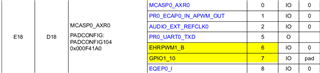
This information is stated in the AM62x Datasheet: https://www.ti.com/lit/gpn/am625
Best Regards,
Anshu