This thread has been locked.

If you have a related question, please click the "Ask a related question" button in the top right corner. The newly created question will be automatically linked to this question.

AM69A: Question About Capacitor Usage in AM69A EVM PROC154E3_RP Circuit

Part Number: AM69A
Other Parts Discussed in Thread: SK-AM69

Tool/software:

Hi Sir,

I have a question regarding the TI AM69A EVM PROC154E3_RP circuit.

I noticed that many capacitors like the NFM15HC105D0G, NFM18HC106D0G, NFM21PC474R1C3D  are used in the design.

Could you please explain the purpose of these capacitors? Is it possible to replace them with regular capacitors?

Thank you.

Best regards,

Gary Yu

  • The capacitors have a very low package inductance and perform better than for example reverse geometry capacitors.  The very low package inductance makes them ideal for power supply decoupling capacitors.  They are recommended but not required.  You can replace with standard 2-terminal capacitors, but it is recommended to perform powrer simulations to ensure the PDN targets are achieved with you power delivery system. 

  • Hi Robert,

    I am currently reviewing the power delivery network (PDN) design for the AM69A EVM (PROC154E3_RP) and noticed the use of multiple low-ESL capacitors (e.g., NFM15HC105D0G) in the circuit. I would like to understand the specific design considerations behind this choice.

    Could you please provide the relevant design specifications or guidelines that define the required number, placement, and type of capacitors for each power rail? Specifically:

    Are there any TI documents or reference designs that specify the recommended capacitor type, value, and count for each power rail?
    Does TI provide PDN simulation models (e.g., SPICE, S-parameters) to validate power integrity when substituting different capacitors?
    Are there any minimum ESL/ESR requirements for decoupling capacitors used in AM69A?
    If we were to replace low-ESL capacitors with standard MLCCs, what are the recommended verification steps to ensure proper power integrity?
    If there are any application notes, reference designs, or simulation tools that could help with this analysis, I would appreciate your guidance.

    Thank you for your support.

    Best regards,

  • Can TI provide design specifications/guidelines that define number, placement, and type of capacitor for each power rail?  [TI - we already have that in our SK-AM69 EVM example, which you can use as a reference.  You can also refer to the TDA4-VH EVM example, as it is similar package/power requirements.]

    Are there any documents which specify capacitor type, value, and count for each power rail? [TI - again I would refer you to our existing hardware designs.  Those designs have been tested across process/temperature and are confirmed to meet an noise specifications.]

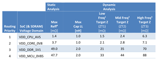
    Does TI provide PDN simulation models to validate power integrity?  [TI - We do not provide a model, but we do provide target impedance parameters for the higher current/low voltage power rails (VDD_CORE, VDD_CPU, VDD_MPU, etc).  We define targets for 3 different freq ranges for each rail.  Also - based on your power estimate for your use-case, you could generate a load step to ensure current to ensure you power delivery system keeps voltage/noise within specifications.]

    Does TI have any minimum ESL/ESR requirements for decoupling capacitors? [TI - No, we use 3terminal caps due to their lower package inductance (better performance), but if you can meet the power integrity specs with standard 2-term caps...then no issue.]

    Does TI have any application notes that can help with power delivery analysis? [TI - Link provides power integrity analysis information.  PPT also includes other information like LPDDR, High Speed IO, etc.  For these better to refer to the dedicated application notes.