Tool/software:
Problem description:
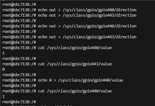
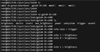
There are problems when trying to test GPIO N20, M21 and V25.
GPIO set output mode, set 0/1, the measurement found that the level does not change;
GPIO set to input mode, external intervention high/low level, read value will not change.
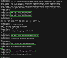
My Operating:
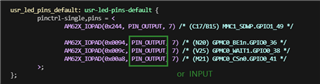
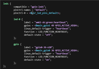
My dts :