Tool/software:
Hi there,
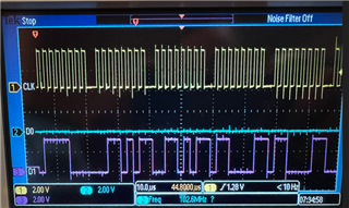
I configure main domain SPI 1's pin M19 (MMC1_DATA0.SPI1_D0) as output and pin M20 (MMC1_CMD.SPI1_D1) as input (see line# 5 and 6 in the dts configuration below). However, when we type SPI test command
spidev_test -v -D/dev/spidev1.0 -p x\55aa55aa
we saw from oscilloscope screen (screenshot is attached at the bottom) that SPI1_D1 became output (i.e., MOSI) and SPI1_D0 became input (i.e., MISO). Did I miss some configuration in device tree below?
Thanks,
Charles
Device tree configuration for SPI1
main_spi1_pins_default: main-spi1-default-pins {
	pinctrl-single,pins = <
		J721E_IOPAD(0x100, PIN_INPUT, 8) /* (P21) MMC1_CLK.SPI1_CLK */
		J721E_IOPAD(0xec, PIN_INPUT, 8) /* (N19) MMC1_DAT3.SPI1_CS0 */
		J721E_IOPAD(0xf8, PIN_OUTPUT, 8) /* (M19) MMC1_DAT0.SPI1_D0 */
		J721E_IOPAD(0x104, PIN_INPUT, 8) /* (M20) MMC1_CMD.SPI1_D1 */
	>;
};

&main_spi1 {
	status = "okay";
	pinctrl-names = "default";
	pinctrl-0 = <&main_spi1_pins_default>;

	spidev@0 {
		spi-max-frequency = <24000000>;
		reg = <0>;
		compatible = "rohm,dh2228fv";
	};
};
Oscilloscope screen shot
D0: spi1_D0
D1: spi1_D1