Other Parts Discussed in Thread: AM62L, SYSCONFIG
Tool/software:
Hi,
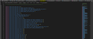
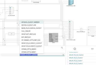
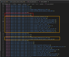
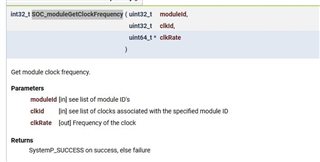
Where can I find the list of module ID's and list of clocks? Seems not clickable like what Am62x does
Thanks,
Dazong
Tool/software:
Hi,
Where can I find the list of module ID's and list of clocks? Seems not clickable like what Am62x does
Thanks,
Dazong