This thread has been locked.

If you have a related question, please click the "Ask a related question" button in the top right corner. The newly created question will be automatically linked to this question.

TIDA-01555: Parallel sampling of 20 nos. of ADS12L11 with Sitara PRU

Part Number: TIDA-01555
Other Parts Discussed in Thread: ADS127L11,

Tool/software:

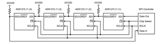
We want to interface 20 nos. of ADS12L11 ADCs to PRU of Sitara processor. 

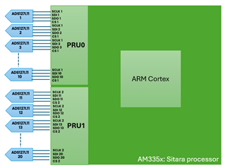
We want to achieve sampling rate of 100 ksps with above architecture with parallel sampling. Can you please let us know whether is it feasible?

To keep additional processing power for future scope, we are thinking to use AM64xx sitara. However, is AM64x support QNX? 

AM64x support quad core cortex R5F and dual core cortex A53 as well. So is it possible to run QNX on R5F and Linux on A53? Anyone using this way?

Thanks and best regards,

Dnyandeep

  • Hello

    I will assign this to PRU experts for the ADC attach query. 

    On QNX, AFAIK there is no QNX support for AM64/AM24 family and none planned from TI side. You should follow up with Blackberry in case they have any offering or something in their roadmap to support AM64. 

  • Any update on PRU? We also explored AM62x and it looks good to us, since it support QNX along PRU running at 333MHz which will help us to achieve higher speed for ADC. 

  • Hi Dnyandeep,

    We already have interfacing a single ADS127L11 example with AM64x in our SDK (Sampling rate of 1MSPS) -EXAMPLES_PRU_ADC_ADS127

    A little bit about PRU - We have 20 GPIO pins on each ICSSG instance (ICSSG0 and ICSSG1) of AM64x, these pins are used by the PRU core to generate the required clock signal and read the ADC data.

    Following the TIDA-01555 implementation, interfacing 10 ADCs to a single PRU will not be possible as we are limited by the number of GPIOs. Tying all CS pins to a single GPO pin for simultaneous sampling and one GPO pin for the ADC clock leaves us with 18 pins for SDO/SDI.

    On AM62x, we have the same PRU GPIOs as AM64x.

    I have added our PADC expert to the thread as well, to provide any other possible implementation for your use case.

    Regards,

    Nitika

  • Hi Dnyandeep,

    Please find the recommendation from the PADC team below:

    The ADS127L11 uses a standard 4-wire SPI interface. Since you only needs to support 100ksps data rate, several ADCs can be connected in daisy-chain.

    You can have 4 parallel SPI configurations, with 5 ADCs in each chain. All 4 chains can share a common CS and SCLK (if that is feasible).

    In addition, there is a DRDY output signal that is typically used as an interrupt to the processor when new data is available. For simultaneous operation, a common START pin connection is used to synchronize all ADCs, and after synchronization, only a single DRDY needs to be connected to the processor since all ADCs DRDY will have the same phase and frequency.

    Assuming you use 4 wires for each SPI connection, and a common START and DRDY,
    you will need - 5 (no. of ADCs in each chain) *4 (number of chains) +2 (START and DRDY) = 22 total IO pin connections.

    You can two of the chains controlled by PRU0 and the other two by PRU1. 

    The ADCs will also require an external clock, but this is usually provided by a dedicated oscillator, but it can be sourced from any clock source with 10ps-rms jitter or less.

    Also, SCLK is limited to a maximum frequency of 20MHz when using daisy-chain. This is due to propagation delays in the ADC.

    You can find more about the Daisy chain connection in the ADS127L11 datasheet section 8.5.8 Daisy-Chain Operation.

    Regards,

    Nitika