This thread has been locked.

If you have a related question, please click the "Ask a related question" button in the top right corner. The newly created question will be automatically linked to this question.

AM62A7: i2c port2 can not scan the device using cmd "i2cdetect -y -2"

Part Number: AM62A7

Tool/software:

I am using the ti am62a7 evm board. right i connect the imx219 to SCO though J20 connector. There are no serdes and deserdes in this line.
Imx219 MIPI connect to SOC MIPI dricty。 
and the setting of the device tree is below. The problem is that i can not using cmd "i2cdetect -y 2" to scan the i2c device in the i2c bus.

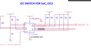
no any nod can be see after cmd ""i2cdetect -y 2”。 I can see that the evm board have a switch board tca9543 in the hardware design. 

Why i can not use this i2c. I need to read some message form sensor in application function. can you share the step how i should do to implement the function

&main_i2c2 {
#address-cells = <1>;
#size-cells = <0>;
status = "okay";

i2c-switch@71 {
compatible = "nxp,pca9543";
#address-cells = <1>;
#size-cells = <0>;
reg = <0x71>;

/* CAM port */
i2c@1 {
#address-cells = <1>;
#size-cells = <0>;
reg = <1>;

ov5640: camera@10 {
compatible = "sony,imx219";
reg = <0x10>;

clocks = <&clk_imx219_fixed>;
clock-names = "xclk";

reset-gpios = <&exp1 13 GPIO_ACTIVE_HIGH>;

port {
csi2_cam0: endpoint {
remote-endpoint = <&csi2rx0_in_sensor>;
link-frequencies = /bits/ 64 <456000000>;
clock-lanes = <0>;
data-lanes = <1 2>;
};
};
};
};
};
};

  • Hello,

    The I2C switch - your code looks good

    Since you are connecting to signals CSI_I2C2_SCL & SDA on header J20, you do have the signal going through an I2C switch:

    It looks like you already did the hard part and set up the i2c-switch in your devicetree file:
    https://e2e.ti.com/support/processors-group/processors/f/processors-forum/1455331/am625sip-i2c-gets-set-up-but-does-not-output-anything/5605384#5605384

    and it looks like you already set the switch to use output 1 instead of output 0.

    What about the pinmux settings? 

    You did not include any pinmux settings inside your &main_i2c2{} devicetree node. Are those included somewhere else? If not, you'll need to add the pinmux settings before you can start to send signals to the I2C peripheral.

    You should see the I2C interface coming up during Linux boot in the boot logs.

    Regards,

    Nick

  • The pinmux is define other place. here is the define:

    &main_i2c2 {
    status = "okay";
    pinctrl-names = "default";
    pinctrl-0 = <&main_i2c2_pins_default>;
    clock-frequency = <400000>;
    };

    main_i2c2_pins_default: main-i2c2-default-pins {
    pinctrl-single,pins = <
    AM62AX_IOPAD(0x0b0, PIN_INPUT_PULLUP, 1) /* (K22) GPMC0_CSn2.I2C2_SCL */
    AM62AX_IOPAD(0x0b4, PIN_INPUT_PULLUP, 1) /* (K24) GPMC0_CSn3.I2C2_SDA */
    >;
    };

    right now. i using Oscilloscope to check the sda and scl. there have signal during running the command "i2cdetect -r -y 2"
    so it seems that the i2c-switch port setting is correct. to verify the problem i have using the command 
    "i2cset -y 2 0x71 0x01 0x01" to control the i2c-switch. and register can be set and can be read.
    and i have check the reset pin. It have be set as high. 
      

    and by the way. when i using the i2cdetect -y 2. there will display below warning.
    Warning: Can't use SMBus Quick Write command, will skip some addresses

    can you share me where should i improve? thanks very much

  • by the way i change the i2c switch by change below device tree.  It can not find the sensor either.

    &main_i2c2 {
    #address-cells = <1>;
    #size-cells = <0>;
    status = "okay";

    i2c-switch@71 {
    compatible = "nxp,pca9543";
    #address-cells = <1>;
    #size-cells = <0>;
    reg = <0x71>;

    /* CAM port */
    i2c@0 {
    #address-cells = <1>;
    #size-cells = <0>;
    reg = <0>;

    ov5640: camera@77 {
    compatible = "sony,imx219";
    reg = <0x77>;

    clocks = <&clk_imx219_fixed>;
    clock-names = "xclk";

    reset-gpios = <&exp1 13 GPIO_ACTIVE_HIGH>;

    port {
    csi2_cam0: endpoint {
    remote-endpoint = <&csi2rx0_in_sensor>;
    link-frequencies = /bits/ 64 <456000000>;
    clock-lanes = <0>;
    data-lanes = <1 2>;
    };
    };
    };
    };
    };
    };

    root@am62axx-evm:/opt/edgeai-gst-apps# i2cdetect -y -r 2
    0 1 2 3 4 5 6 7 8 9 a b c d e f
    00: -- -- -- -- -- -- -- --
    10: -- -- -- -- -- -- -- -- -- -- -- -- -- -- -- --
    20: -- -- -- -- -- -- -- -- -- -- -- -- -- -- -- --
    30: -- -- -- -- -- -- -- -- -- -- -- -- -- -- -- --
    40: -- -- -- -- -- -- -- -- -- -- -- -- -- -- -- --
    50: -- -- -- -- -- -- -- -- -- -- -- -- -- -- -- --
    60: -- -- -- -- -- -- -- -- -- -- -- -- -- -- -- --
    70: -- UU -- -- -- -- -- UU
    root@am62axx-evm:/opt/edgeai-gst-apps# ^C

  • Hello,

    I might be misunderstanding something. It looks like everything is working correctly.

    In your second response, it looks like i2cdetect is giving exactly the output we would expect. You define 2 peripherals on the I2C bus at 0x71 and 0x77, and i2cdetect is telling us that there are Linux drivers attached to peripherals at 0x71 and 0x77: https://e2e.ti.com/support/processors-group/processors/f/processors-forum/1373630/sk-am62b-p1-assistance-required-for-eeprom-i2c-0/5247131#5247131

    Regards,

    Nick